Here’s a really useful and easy project you can do with an Arduino. If you have a hard time reading the color bands on resistors like I do, this project is perfect for you. Instead of struggling every time you need to find the resistance of a resistor, just build an Ohm meter and measure all of your resistors. If you come up with a good way to label and organize them, you’ll never need to spend time guessing the difference between those tiny grey and purple bands again.
Wiring the Ohm Meter
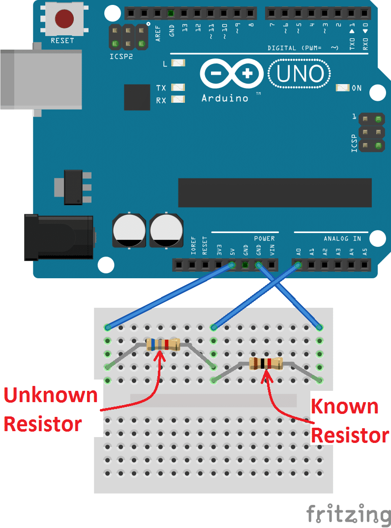
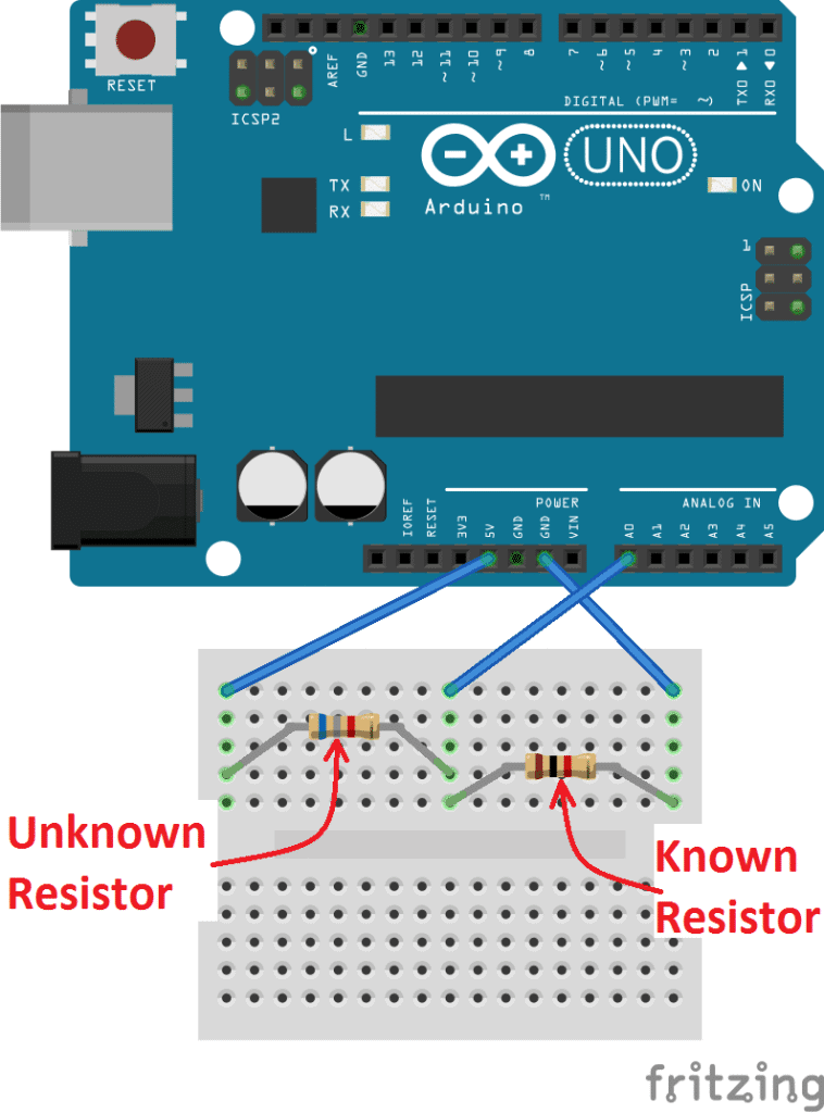
The circuit is really simple. All you need is an Arduino, the resistor you want to measure, and another resistor with a known value. We’ll set up a voltage divider with the known and unknown resistors, and measure the voltage between them with the Arduino. Then we’ll run a program that will calculate the resistance from Ohm’s Law.
First, wire up the circuit like this:
The Code
Now, enter this code into the Arduino IDE and upload it to your board:
int analogPin = 0;
int raw = 0;
int Vin = 5;
float Vout = 0;
float R1 = 1000;
float R2 = 0;
float buffer = 0;

void setup(){
Serial.begin(9600);
}

void loop(){
  raw = analogRead(analogPin);
  if(raw){
    buffer = raw * Vin;
    Vout = (buffer)/1024.0;
    buffer = (Vin/Vout) - 1;
    R2= R1 * buffer;
    Serial.print("Vout: ");
    Serial.println(Vout);
    Serial.print("R2: ");
    Serial.println(R2);
    delay(1000);
  }
}
Enter the value of your known resistor (in Ohms) on line 5 of the code above. In my case, I’m using a known resistor with a value of 1K Ohms (1000 Ohms). Therefore, my line 5 should look like this: float R1 = 1000;.
The program sets up analog pin A0 to read the voltage between the known resistor and the unknown resistor. You can use any other analog pin though, just change the pin number in line 1, and wire the circuit accordingly.
When you open up the serial monitor you’ll see the resistance values printed once per second. There will be two values, R2 and Vout.
R2: is the resistance of your unknown resistor in Ohms.Vout: is the voltage drop across your unknown resistor.
Output the Readings to an LCD
One reader commented that they would like to display the resistance measurements on an LCD. This is easy to do. First you’ll want to read our tutorial on setting up an LCD display on the Arduino. That will show you how to connect everything. After you’ve got the LCD set up, connect the Ohm meter as shown above, and upload this program to the Arduino:
#include <LiquidCrystal.h>
LiquidCrystal lcd(12, 11, 5, 4, 3, 2);

int analogPin = 0;
int raw = 0;
int Vin = 5;
float Vout = 0;
float R1 = 1000;
float R2 = 0;
float buffer = 0;

void setup(){
  lcd.begin(16, 2);
}

void loop(){
  raw = analogRead(analogPin);
  if(raw){
    buffer = raw * Vin;
    Vout = (buffer)/1024.0;
    buffer = (Vin/Vout) - 1;
    R2 = R1 * buffer;

    lcd.setCursor(0, 0);
    lcd.print("Vout: ");
    lcd.print(Vout);

    lcd.setCursor(0, 1);
    lcd.print("R2: ");
    lcd.print(R2);
    delay(1000);
  }
}
How Accurate Is It?
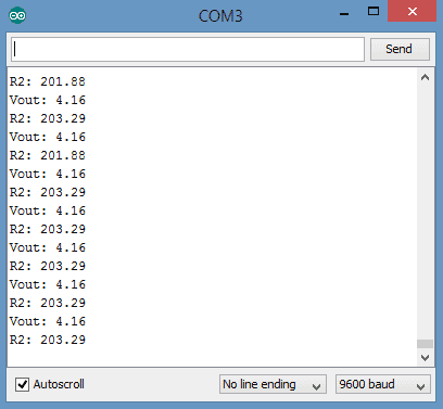
These are the readings I got with a 200 Ohm “unknown” resistor:
The values are pretty accurate, that’s only an error of 1.6%.
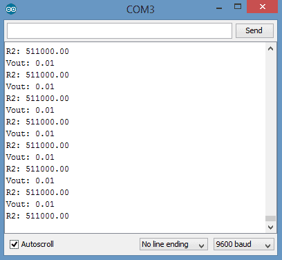
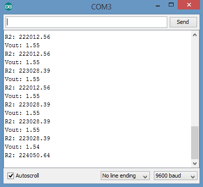
However, these are the readings I got when I measured a 220K Ohm “unknown” resistor:
The error here is greater than 100%.
That’s because I was still using a 1K Ohm known resistor. The accuracy of the Ohm meter will be poor if the value of the known resistor is much smaller or larger than the resistance of the unknown resistor.
The problem is easily fixed by using a known resistor that’s closer in value to the unknown resistor. Once I replaced the 1K Ohm known resistor with a 100K Ohm resistor, the accuracy of the measurements improved greatly.
Don’t forget to change the code above (where it says float R1 = 1000) to the value of your new known resistor.
These are the values I got with the same 220K Ohm “unknown” resistor and a 100K Ohm known resistor:
These values are much more accurate, with an error of about 1.8%.
Here’s a video tutorial for this project if you want to see the Ohm meter working:
This project should help you identify your resistors without the guesswork involved in reading color bands. I just measured all of my resistors and wrote the resistance value on the paper strips holding them together. It’ a lot easier than looking at the color bands every time you need a certain resistor!
If you’re having trouble with this project, just leave a comment below and I’ll try to answer it… And if you liked this tutorial, be sure to subscribe and we’ll send out an email to let you know when we publish new articles!





Why do I need to subtract 1 in line 21?
Because the formulae is Vin/Vout = R1/(R1+R2), with some algebra, you’ll end up with R2 = (Vin/Vout – 1)*R1.
Actually, the original equation is:
Vout / Vin = R1 / (R1 + R2)
Cross multiply:
Vout * (R1 + R2) = R1 * Vin
Divide both sides by Vout:
R1 + R2 = (R1 * Vin) / Vout
Subtract R1 from both sides:
R2 = ((R1 * Vin) / Vout) – R1
Simplify the right side:
R2 = (Vin / Vout – 1) * R1
I know this post is old, and correct me if I’m wrong, but isn’t the formula for a voltage divider: :
Vout / Vin = R2 / ( R1 + R2 )
And simplifies down to:
R2 = R1 / ( ( Vin / Vout ) -1 )
which would change your Arduino code from:
R2 = R1 * buffer;
to:
R2 = R1 / buffer;
Just wanted to point this for anyone who’s calculations show errors like mine did using a 10 ohm constant (R1) and 37.6 ohm “unknown” (R2) with the above math.
Your expression would be right if R1 (known resistor) would be connected to Vcc and R2 (unknown resistor) would be connected to GND. But in this schematics the resistors are swapped so unknown resistor is connected to Vcc and the known one is connected to GND. You obviously connected the unknown resistor to GND so that is why you got wrong results. You can either swap the resistors or change the expression as you already did.
What exactly is raw?
See my comment below – it didn’t attach as a reply for some reason.
Excellent, just what i need after a day of tinkering to sort my resistors, far easier and quicker than using my multimeter
Hi, I used your schematics to try to detect a broken resistor in my 3D printer (the one heating the plastic);
Your circuitry was tested on various resistance and all the values displayed were correct.
Then I put 2×100 kOhms resistance in series to have a 200kOhms equivalent resistance (because the printer resistance is 100 kOhms, I was told) and the values displayed were then weird : Vout=0.1 to 0.12 max and R2= several MOhms… I also tried with only one 100 kOhms resistance, same kind of values.
What can I conclude ?
Thanks in advance.
First, check all your connections, and also verify that you have updated the sketch with the new resistance value for R1. If it still doesn’t work after that, I would conclude that you have a bad resistor or your analog pin 0 has somehow been damaged (the latter is really unlikely). A voltage divider works by sinking a portion of the voltage in the circuit back to ground. Since electricity follows the path of least resistance, the point directly before R1 is Vin (5V on this setup), after R2 is 0V (connected to ground), and between R1 and R2 is Vout (the amount not being sunk to ground by R2).
You could test to see if it’s a problem with analog pin 0 by removing R2 from the circuit. This should give you a Vout of 5V (since none of the voltage is sunk to ground), and an R2 of 0 (which is actually infinity). If this works properly, it’s probably a bad resistor that you’re trying to check, or a very big resistor, in which case you need to have a bigger R1 to get reliable values. If this doesn’t work properly, then your analog pin 0 is messed up.
If it’s your analog pin, simply moving the wire from analog pin 0 to analog pin 1, and modifying line 1 of the sketch to match your new analog pin should fix the problem. If that doesn’t fix it, then either your entire Arduino is screwed up, or it’s your connections. If it’s your connections… well, that should have been the first thing you checked!
raw= analogRead(analogPin1);
if(raw)
{
buffer= raw * Vin;
Vout= (buffer)/1024.0;
x= Vout/Vin;
R2= x * R1 / (1 – x );
Serial.print(“Vout: “);
Serial.println(Vout);
Serial.print(“R2: “);
Serial.println(R2);
delay(1000);
}
Hi sir, is it possible to read the value of the resistors in a LCD? Can you make a code for it. PLease thank you
I mean can i display it to a LCD instead of the serial monitor?
hello john so to display the value of resistance into arduino ohmmeter using LCD is very simple, you need just to some kind of simple codes in your sketch so i will be helping you uploading the full sketch including printing the values in LCD so let me a bit later to do it and upload it very soon
Hi John, I just added a section to the post that explains how to output the resistance measurements to an LCD. Hope that helps…
can we use a different resistor value?
“: How to Make an Arduino Ohm Meter https://t.co/4VNFdTSegy #arduino #diyelectronics https://t.co/2BluYBh7cr“
i’m using 278k R1 and measuring a 5k resistor and the reading jumps up and down 400 ohms or less. what could cause this, i tried a second uno and soldering all wires.
400 ohms is under 10% tolerance (8% to be exact) on a 5k ohm resistor. It’s likely that your resistor has a tolerance of 10-15%, and this is well within that boundary. Additionally, if your 278K resistor also has a 10% tolerance and you have not measured its resistance exactly before using it in your project, there’s a possibility that this could throw your calculations off as well.
thanks anyway but another kind man solved my problem. my accuracy was improved when both resistors were close in value because of the nature of the voltage divider used in the circuit.
muy bueno very good
In this sketch, the value of “raw” is set by doing an analogRead of pin 0, which is connected to the wire coming out between the resistors. This value is a 10-bit analog representation of 0-5V. This means that it will be some value between 0 and 1023. To get the actual voltage value (or at least as close as we can get with a 10-bit resolution), we multiply times Vin, then divide by 1024. So, if the voltage read at pin 0 is 2.4V, it will be read into raw as 492. So with the equation:
Vout = (raw * Vin) / 1024
raw = 492, Vin = 5
Vout = (492 * 5) / 1024
Vout = 2460 / 1024
Vout = 2.40234375
The value provided is close enough to be worth using unless you need ultra-precise measurements. With the Arduino Due and Zero, you can change the analog resolution to a 12-bit number, giving you values between 0 and 4095 if you need more precision.
“: How to Make an Arduino Ohm Meter https://t.co/4VNFdTSegy #arduino #diyelectronics https://t.co/8dykWRpr00“
I was trying to adapt this to read a negative earth variable resistor, common in automobiles and one wire sensors so more useful than the current circuit. my algebra is a bit rusty but change the following lines and there you go. fixed resistor is now R2.
float R1= 0;
float R2= 1000;
R1=R2/buffer;
Serial.print(“R1: “);
Serial.println(R1);
Hello. I noticed that the resistance data is not as stable as in real ohm-meter. Is there possible way to improve that?
Hi, I made a 6 channel ohm meter but I am getting non consistent readings (around 2k). I tried to allow more time (5 milliseconds) between readings to allow the ADC to settle, I changed the reference resistor to closer to the measured one and I even tried to rewire the circuit but still getting fluctuating values for the same measured resistors. Im wondering if I need to implement some digital filtering (averaging a few samples, discarding peak values etc). I did notice in the screen shots the values are consistent.
Any suggestion appreciated…
Hi oryaninbar ,
Can you post your code?
hi oryaninbar, I also experienced the same problem like you. and I am also thinking to do some low filter to discard a fluctuate value from the resistance.
Do you already solve your problem regards to the fluctuate value? If yes, could you tell me how you solve that. much appreciate your reply. Thanks
Thanks for sharing this.. work for me ,together with lcd i2c …tks again.
Can you link how to convert this project with output on 16×2 lcd?
Can I use an external 12V power supply for this type of measurement? I wanted to use Arduino to control electric windows in my car. However, the button panel operates at 12V and uses resistors to communicate which button has been pressed.
There is an interesting thing going on when you try to use 12 ohm for R1 and 1 ohm for R2. For some reason, when I connect the R2 to earth, (R1 is connected to 5V from arduino) the lcd turns off and all the power goes to R1 and it starts to heat up. As soon as I remove the ground, the lcd turns back on. I don’t know if arduino’s adc were runing while the lcd was down. Any suggestion on why this happened? This does not happens when 1k+ resistors are used.
Hi, using a 10000 ohm as known resistor and a LED as unknown resistor
I find Rled = 4202.5 [ohm] / Vout = 3.52 [v]
aiming to verify the result I used the equation R2/R1 = (Vin/Vout) -1, and the measured resistance (Rled = 4202.5 [ohm])
I verified the measured voltage Vout = 3.52 [v].
applying voltage divider in the circuit (using an op. amplifier) gives the following equation
Vout/Vin = (R1+R2)/R1 which is different from the Vout / Vin = R1 / ( R1 + R2 ).
Where am I wrong?
P.S If the circuit is needed I can send you by email.
Thank you in advance,
PD
If V out / Vin = R1 / (R1 + R2) is the right form of voltage divider equation
keeping in mind that V out is the voltage drop across your unknown resistor R2
Isn’t it better to write : V out / Vin =R2/ (R1 + R2) ?
Thank you in advance
unable to read LDR values
Hi, thank you for the instructions. I want to ask some issues I encountered. So the known resistor I used is 10000 ohms and I am trying to measure one million ohm resistance. The value deviates quite significant. It shows 1.27 millions and 1.45 million ohm. May I know how it can happen and what I can do to handle this?
is the coding same as arduino nano bcs and this is the error that pop out
Arduino: 1.8.5 (Windows 10), Board: “Arduino Nano, ATmega328P”
collect2.exe: fatal error: cannot find ‘ld’
compilation terminated.
exit status 1
Error compiling for board Arduino Nano.
This report would have more information with
“Show verbose output during compilation”
option enabled in File -> Preferences.
Hi am impressed with your circuit, but am trying to measure the resistance earth or ground pls help me out pls friends pleased help me out thanks expecting hearing from you.
Hi,
Cool trick. I’m trying to obtain a resistance value for a resistor-type temperature sensor. However the values vary from around 45Kohm to 100ohm. Is there any way to modify the reference circuit so that the accuracy remains within acceptable limits (+/- 5%) accross this range?
This is awesome, i do have another question now though, lets assume, that you measure 100 Ohms( this can and will fluctuate ), but , i want the arduino to ( possibly via a digital pot) output a resistance of 90 Ohms , is this a possibilty?
If we don’t know the value of the unknown resistor, how can we choose the reference resistance value?
Hi I’m trying to use this voltage divider model to measure the resistivity of an unknown material, I’m having trouble understanding what the point of the buffer in the code is and why you divide by 1024 in lines 22-25?
Does the buffer just put make it so the scale of the input and output are similar? Also where does the 1024 come from? I’ve been trying to look it up but I cannot find it
i know this is kind of an old post, but this isn’t working for me when i use 3.3V instead of 5V, even though i changed the setup code from float Vin = 5; to float Vin = 3.3; and changed the circuit to reflect the change, i.e. when i use a 1k Ohm known resistor and a 330 Ohm “unknown” resistor, the program says it’s resistance is 1077 Ohms. When I use 5V, however, the program outputs 338 Ohms, which is much closer to the actual resistance
If you define raw as a float you can simplify the entire calculation into a single line. Also voltage isn’t actually needed in this case because it cancels out.
R2= R1 * ((1024/raw)-1);
Great code however am having strange output
For the source value of 220 I have a known R2 of 10 Ohm
but the output from the following code is showing 5274. With the difference between 220 and 10 not that great why is the code showing over 5K?
int analogPin= 0;
int raw= 0;
float Vin= 5;
float Vout= 0;
float R1= 220;
float R2= 0;
float buffer= 0;
String inString =””;
void setup()
{
Serial.begin(9600);
}
void loop()
{
raw= analogRead(analogPin);
if(raw)
{
buffer= raw * Vin;
Vout= (buffer)/1024.0;
buffer= (Vin/Vout) -1;
R2= R1 * buffer;
Serial.print(“Vout: “);
Serial.println(Vout);
Serial.print(“R1: “);
Serial.print(R1);
Serial.print(” -R2: “);
Serial.println(R2);
delay(4000);
}
while (Serial.available() > 0) {
int inChar = Serial.read();
if (inChar != ‘\n’) {
// As long as the incoming byte
// is not a newline,
// convert the incoming byte to a char
// and add it to the string
inString += (char)inChar;
}
// if you get a newline, print the string,
// then the string’s value as a float:
else {
Serial.print(“Input string: “);
Serial.print(inString);
Serial.print(“\tAfter conversion to float:”);
Serial.println(inString.toFloat());
R1 = inString.toFloat();
// clear the string for new input:
inString = “”;
}
}
}
Ian, you likely have your resistors in the wrong locations in the circuit. 220/10 = 22 and 5K/220 is approximately 22. The circuit is set up so that your unknown resistor (10 for you) goes between 5V and the analog input, while the known resistor (220 for you) goes between the analog input and ground. If your circuit is built correctly, you should have Vout = 220/230*5 = 4.78 V. If you have the resistors reversed, you will have 10/230*5 = 0.22 V for Vout, and R2 will be 22*220 = 4,840 Ohms.
Hello!
Can someone please make a comment next to every line in the code so we can understand it faster and easier?
Thanks in advance!
commenting on every line is messy and unnecessary.
just spend more time learning how to code in C# and how the arduino API.
The program just reads the value at A0 analog pin and does some elementary math to estimate the unknown R value.
then it sends the data though the serial port so you can read it on your serial monitor window.
im going to complicate it by having it test 4 points simultaneity on a pcb i assemble and output that to an LCD.
it still wont be too hard.
I am looking to make a device for my workplace that compares a known resistance value to the total resistance of an unknown pot. Instead of having a serial monitor, I would like to illuminate a red LED if the pot is above +/-15% of the known resistance and illuminate a green LED if the pot is within +/-15%. Can anyone provide some insight into this?
Is it possible to build this in a wheatstone setup to measure low resistance resistors accurately?
Is it possible to switch the known and unknown resistor and still make this work? the device I want to measure has one side of the un known resistor tied to ground