Switches make or break connections in a circuit. They also allow users to change the path of the current flow by interrupting or diverting it. In short, it can connect and disconnect a conducting path or activate and deactivate different features of a circuit. In every electronics application, having a control system is vital. And control systems cannot perform an operation without these switches.
A switch works through contacts; when contacts are touching, current can pass through them. Otherwise, there will be no current flowing throughout the circuit. Contacts may operate alternately, simultaneously, or sequentially. A switch can be operated manually or electronically.
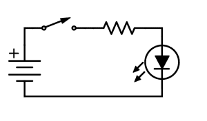
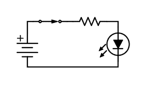
Below are diagrams showing an open and closed switch. These diagrams use the most common switch in simple circuits, the SPST switch. Basically, these are diagrams showing the on and off state of the circuit.
Switches by Type of Actuator
Toggle Switches
Switches that are controlled by handles or levers to control the flow of the electric current or electric signal are called toggle switches. These switches are manually actuated by the handle or the lever. It is a hinged switch that can assume the position of two conditions – ON and OFF.
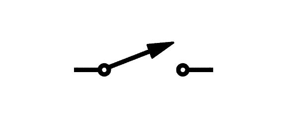
Being easy to operate, toggle switches are used in a number of different applications. They are used for commercial and household appliances and are commonly used as light control switches. Some toggle switches also have flip covers to guard against or to prevent false switching. Because it is an on-and-off switch, it is represented by the symbol SPST switch in diagrams as shown below. The example schematic diagrams above used a toggle switch.
Push-Button Switches
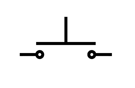
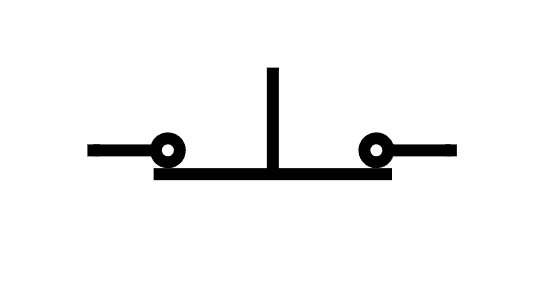
Momentary push button switches are switches that only remain at a certain state unless actuated. These switches may be normally open or normally closed. The first image below is a normally open push-button switch while the second one is a normally closed push-button switch.
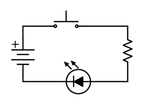
Below is an example of a schematic diagram using a normally open push button switch.
Rotary Switches
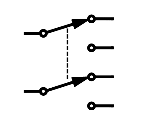
A rotary switch is a switch operated by rotation. Rotary switches have a rotating spindle. As the name implies, rotary switches are operated by turning a knob or a rotating spindle. They move in a circle and can stop in several positions. Selecting the correct position enables the relevant connections. As rotary switches can have many positions, they enable a particular point to be connected to one of a number of points in the electronics circuit.
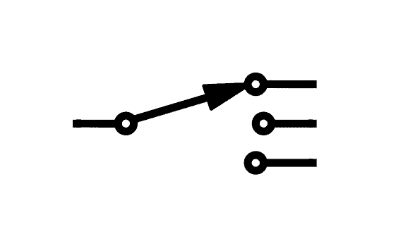
While rotary switches can be found on many types of industrial equipment, they can also be found in consumer equipment such as cars for adjusting things like fan speed and washing machine timer. Since complex switching operations are more available and used nowadays, rotary switches are becoming less common. However, these switches are still used and available. Below is a schematic symbol for a three-position rotary switch.
Magnetic Reed Switches
Magnetically-operated switches are called magnetic reed switches. These are small electromagnetic switches used to control the flow of electricity in a circuit. When these devices are exposed to a magnetic field, two ferrous materials inside these pull together and closes the switch. Without exposure to a magnetic field, the reeds separate, thus opening the switch. This makes it a great non-contact switch.
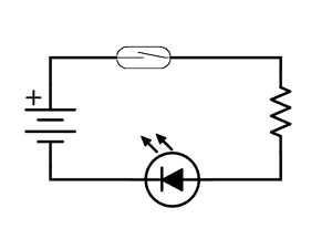
Indoor and window sensors for burglary alarm systems usually use magnetic reed switches. Standard reed switches are SPST. Below is the schematic symbol of a standard reed switch.

Below is an example of a schematic diagram using a magnetic reed switch.
DIP Switches
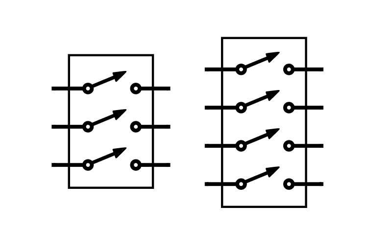
DIP switches or dual in-line package switches change the operating mode of a device through its positions. These are manual electric switches packaged in a group in a standard line package. They are often used as an alternative to jumpers because they are easier to operate and less likely to get lost. DIP switches are commonly used to set security codes on garage door openers. There are many different kinds of DIP switches. Some of the most common are the slide, rocker, side, and rotary types.
DIP switches are still widely used for industrial equipment because they are inexpensive and easy to incorporate into circuit designs even though their popularity has been decreasing. Below are schematic symbols of DIP with three and four actuators.
Switch Configurations
Familiar with SPST, SPDT, DPST, and DPDT switches? These are actually types of switches based on their configuration.
The connection they make within the circuit defines these types of switches. They are classified based on the number of poles and throws. Poles are the number of circuits that can be switched while throws are the number of positions that a switch can adopt. The number of throws represents the number of states by which current can pass through the switch.
SPST Switches
A SPST (Single Pole, Single Throw) switch is an on and off switch. Single circuits commonly use this type of switch.

SPDT Switch
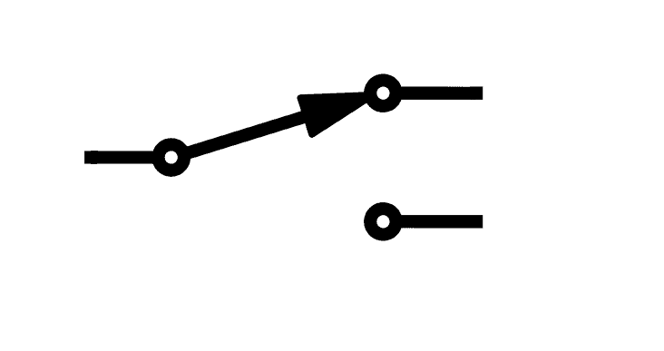
A SPDT (Single Pole, Double Throw) switch is a two-way switch. Using this switch, there can be two routes of current flow and it depends on the position of the switch.
DPST Switch
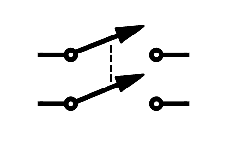
A DPST (Double Pole, Single Throw) switch has two inputs and two outputs. This switch allows for control of two outputs– either both on or both off since it is a single throw switch.
DPDT Switch
A DPDT (Double Pole, Double Throw) switch has two inputs and four outputs. The inputs have two corresponding outputs to which it can make contact with or connect to.
Thanks for reading! Leave a comment below if you have any questions…


