
The 555 timer could easily be the most common chip used in DIY electronics projects because it’s small, inexpensive, and very useful.

It’s considered a timer because it can output pulses of electrical current for exact amounts of time. For example, it could be used to turn an LED off exactly 5 seconds after a button is pressed. It can also make an LED blink on and off, or generate higher frequency pulses that will make sound when connected to a speaker.
This is the first article in a series where we’ll look into the three different modes of the 555 timer – monostable, bistable, and astable. Each mode has different characteristics that determine how the 555 timer outputs current. In this tutorial, I’ll discuss the monostable mode, but check out our articles on the astable mode and bistable mode as well.
Here’s the 555 timer’s datasheet for detailed technical information:
Monostable Mode of the 555 Timer
In monostable mode, the 555 timer outputs a single pulse of current for a certain length of time. This is sometimes referred to as a one-shot pulse. An example of this can be seen with an LED and a push-button. With one press of the button, the LED will light up, then turn off automatically after a predetermined length of time. The time the LED stays on depends on the values of a resistor and capacitor connected to the 555 timer. The time can be calculated from the equation:

Where t is the length of the electrical output in seconds, R is the resistance of the resistor in Ohms, and C is the capacitance of the capacitor in Farads.
As you can see from the equation, the length of the electrical output can be increased by using larger resistor or capacitor values. The opposite is also true. You can get a shorter output pulse with smaller resistor or capacitor values.
A One-Shot LED Timer
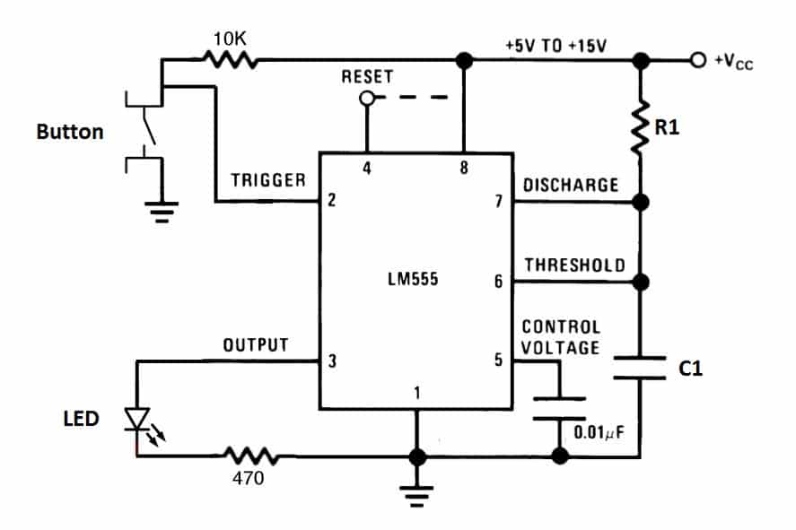
To observe the monostable mode of the 555 timer, let’s build a simple one-shot timer that will turn off an LED after a certain length of time. Use the diagram below to connect the circuit:
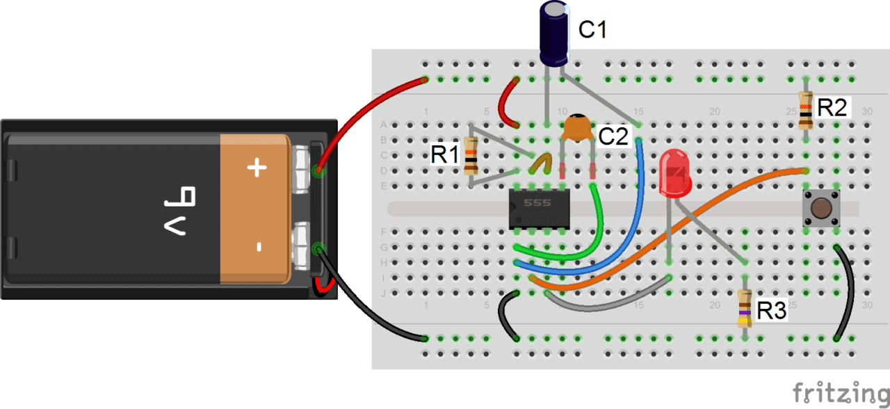
- R1: 10K Ohms
- R2: 10K Ohms
- R3: 470 Ohms
- C1: 470 μF
- C2: 0.01 μF
In this circuit, after you press the button once, the LED will light up then turn off after about 5 seconds. The values of R1 and C1 determine how long the LED stays on:

How Monostable Mode Works
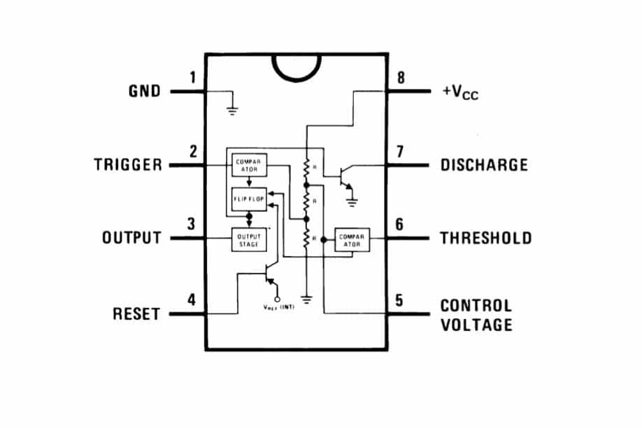
- Pin 1 – Ground: Connected to 0 V
- Pin 2 – Trigger: Turns on the output when the voltage supplied to it drops below 1/3 of Vcc.
- Pin 3 – Output: Outputs up to 200 mA of current at about 1.5 V.
- Pin 4 – Reset: Resets the timing operation of the output when it is connected to ground (0 V).
- Pin 5 – Control: Controls timing output independently of the RC circuit when the voltage supplied to it is above 2/3 Vcc. When not in use, it is usually connected to ground via a 0.01 μF capacitor to prevent fluctuations in timing of the RC circuit.
- Pin 6 – Threshold: Turns off the output when the voltage supplied to it reaches above 2/3 Vcc.
- Pin 7 – Discharge: When output voltage is low, it discharges the capacitor in the RC circuit to ground.
- Pin 8 – Vcc (supply voltage): Can range from 4.5 V to 15 V.
Before the button is pressed, the voltage at the trigger pin is high. Whenever the trigger pin voltage is high, the discharge pin allows current to flow to ground and prevents charge from building up on capacitor C1.
When the button is pressed, the voltage at the trigger pin drops low. Whenever the trigger pin voltage is low, the output pin turns on. At the same time, the discharge pin stops the flow of current from C1 to ground, allowing it to charge.
C1 takes time to charge though, and while the voltage across it is below 2/3 Vcc, the threshold pin remains low so the output pin stays on. When the charge finally builds up enough to make the voltage across C1 greater than 2/3 Vcc, the threshold pin switches off the output pin. At the same time, the discharge pin switches back on and prevents the capacitor from charging until the button is pressed again.
The length of time the LED remains on is a function of the time it takes for the capacitor to become charged to 2/3 Vcc. It’s also determined by R1, since the resistor prevents the flow of current to the capacitor and thus increases the time it takes for the voltage across it to reach 2/3 Vcc.
You can watch this video to see the circuit above in action:
A Variable One-Shot LED Timer
A good way to observe the dependency of time on resistance in this circuit is to replace R1 with a variable resistor (potentiometer):

If you adjust the potentiometer, you should see that the LED starts blinking faster or slower. The effect is quite dramatic. For a great resource on the 555 timer, OpAmps, and other IC’s check out the Engineer’s Mini Notebook: Timer, Op Amp, and Optoelectronic Circuits & Projects. There are 24 different 555 timer circuits in this book!
Click here to continue on to part 2 of this series, 555 Timer Basics – Bistable Mode.
If you have any questions about this circuit, or are having trouble getting it to work, please leave a comment below. And be sure to subscribe to get an email when we publish new posts!


Also, the discharge pin closes and stops C1 from draining to ground
shoul be:
Also, the discharge pin opens and stops C1 from draining to ground
Thanks Colin! You are right, the discharge pin opens, not closes to stop C1 from draining to ground. The post has been updated…
if you used 100uF capacitor in the video why did you write 470uF in the text???
Either capacitor will work, it will just change the time the LED stays on. A larger value capacitor will discharge more slowly, and make the light stay on longer.
Where did you get those breadboard cables? Thanks for the great tutorial.
I have a Question (I’m just now starting to get into electronics,so if this is a stupid question, im sorry. But the way I see it if I don’t ask the question I’ll never know the answer) is it possible to use a triple 5 i c as a low voltage relay?
I’m new too, but… The 555 is considered a “logic” device, not for any significant amperage. A logic relay, yes. Max wattage (e.g., 600 mW max) is in the spec sheet (example = http://www.ti.com/lit/ds/symlink/lm555.pdf)
Is it possible to make the led turn off while still holding the button?
I am a beginner here, and I’m wondering if it is possible to alter this design so that a 10kHz tone at 1V is emitted for 5ms, instead of lighting an LED?
This might be possible with two 555 timers, one in monostable mode set to 5 ms, controlling the Vcc of the second timer in astable mode set to 10kHz.
Could you say please how to add one more time mode, for exp. 15 and 20 seconds, maybe to add one more resistor but how to change modes and connect this resistor?
Hi Alex, if you place another resistor in series with resistor R1 from the diagrams above, you will increase the resistance and increase the time the LED stays on. If you put another resistor in parallel with resistor R1, you will decrease the resistance and decrease the time the light stays on. Hope that helps!
would you eliberate it in better way
Hello i have ckt which have 555.the ckt is on from 5 seconds to 18 seconds.i use potentiometer of 100k and capacitor of 1000uf,volts.now i want to increase timing from 5 seconds to 99 seconds.what changes i havt to do.plz tell me the value if pot and capacitor.plz help me.very urgent
t = 1.1RC
t = time in second
Use Variable resistor 500k resistor like “504” and use 3000uF capacitor.
if R is 100k and C is 3000u,
then time taken = 1.1x100kx3000u = 330s = 5mins 5secs.
If R is increased, on time is also increased.
Variable resistor has 3 pins and use middle one and one of the rest ones to connect.
Love 555 chips and the old 7401 chips
Is there any way to set the timer without pressing a button? Eg using the output from a logic gate? Also is there a way to set it so that the light is on the whole time and after the time (eg 2 minutes) it turns off and stays off?
The purpose of the button is just to drop the voltage at the trigger pin. I think if you replaced the button with a transistor, you could control the circuit with the output of a logic gate. I’m not sure about the second part of your question though.
where is the description?
I have tried assembling the monostable mode circuit above and it worked.
Now I wanted to use this for glow plug heating of my diesel car. My problem is how to utilize this monostable circuit to drive or activate a Bosch mini relay. I would appreciate if you could provide me a circuit diagram as I need it very badly. Thank you very much for your help.
I’m sure that’s possible, the output of the monostable circuit can be used to trigger a relay. You would just need to know the voltage required to activate your relay, and which pin on the relay is used to activate it. That information should be in the datasheet.
https://play.google.com/store/apps/details?id=au.com.hpo.timertool
I constructed this circuit and it works fine, however when turn the potentiometer all the way down I noticed the 555 timer gets very hot. I’m certain this is because too much current is getting through. Is there anyway to avoid this problem so I don’t ruin my 555 timer?
IF I USE 12 v battery?? does this circuit still applicable? if not what component do i need to change??
I’m using 20 sec now. But i have a problem. When i perss button again in 10 sec from running. The timer isn’t reset to 20 sec again. I need to reset 20sec when the button is press again.
Nice little write up. I am not sure the statement about the output pin voltage is accurate. The article claims the voltage will be around 1.5 volts. I think it will actually be pretty close to VCC. If it were only 1.5 volts, I do not think the LED would even light up since even red LEDs have a forward voltage drop of around 2.2 volts. Anyway, thanks for the write up.
What kind of LED is used for this project? I went to the store to get all the items but the LEDs come in different ranges.
The one I got is 2.8V, 20ma
I think I can figure out what resistors I need to make it work if I know what kind of LED was used originally.
is it possible for a circuit containing 555 timer(s) to output a signal for 3 seconds and don’t give anything else for 11 seconds.
(i.e. the motor needs to turn for~3s after a button is pushed, then no matter how many times/long this button is pushed after the first press nothing will happen until 11s fron ths first push has elapsed)
kinds of complicated but i would appreciate the help! :)
Can we make the timer IC off if a switch is used instead of push button which is continuously pressed ?