
Making an LED blink is the “hello world” of microcontroller programming. It’s one of the first things to do when learning to program a new microcontroller. The methods used to connect and program LEDs are very similar to the methods used to control other devices like motors, relays, and buzzers.

In this article, we will learn how LEDs work, how to connect LEDs to an Arduino, how to make LEDs blink on and off, how to control the speed of a blinking LED, and how to control multiple LEDs at the same time. We’ll also learn how to control an LED with a push button and how to use a photoresistor to control the blinking rate of an LED.
Watch the video for this tutorial:

How LEDs Work
Diodes only let electrical current flow in one direction. They’re like a one way valve for electricity. This is the schematic symbol of a diode:

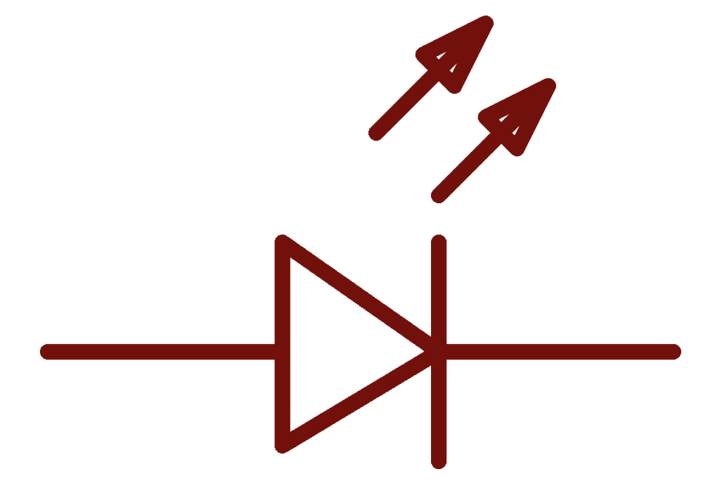
Light emitting diodes (LEDs) are actually a type of diode. They only let current flow in one direction. But unlike diodes, LEDs emit light when current flows through them. This is the schematic symbol of an LED:
LED Polarity
Since current can only flow in one direction, LEDs have polarity. This means they need to be connected the right way around or they won’t work. The side of the LED that connects to a positive voltage is called the anode. The side that connects to ground is called the cathode:
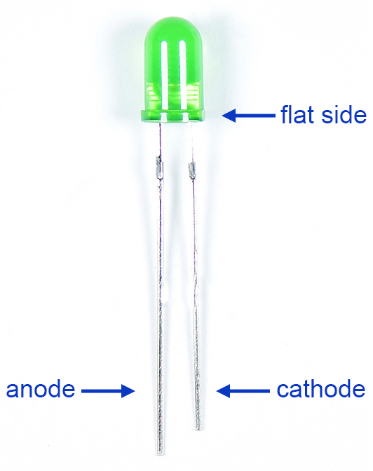
The longer wire is the anode and the shorter wire is the cathode. One side of the LED plastic might be flat, which indicates the cathode.
Current Limiting Resistors and LED Brightness
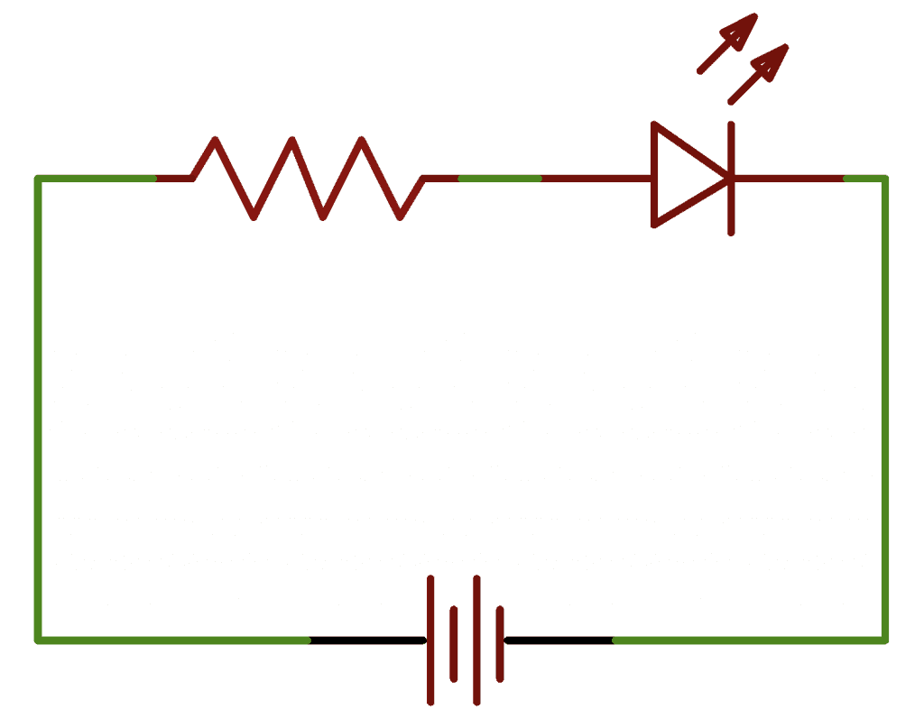
The brightness of an LED is determined by how much current flows through it. More current makes the LED brighter, and less current makes it dimmer. But there’s a limit to how much current can flow through an LED. They will quickly burn out if too much current is allowed to pass through them. To limit the flow of current, we use a current limiting resistor in series with the LED and the power source:
The value of the current limiting resistor affects the brightness of the LED. Higher resistor values restrict the current flow and make the LED dimmer. Lower resistor values allow more current to flow, which makes the LED brighter.
Typical current limiting resistor values start at around 200 Ohms and can be anything up to about 47K Ohms, depending on how dim the LED needs to be. The brightness can also be adjusted in real time by using a potentiometer as the current limiting resistor.
Electrical Signals
The Arduino communicates with other devices by switching on and off electrical current. When current is switched on, it’s known as a high signal. When the current is switched off, it’s known as a low signal. The length of time the current stays on or off can be changed from nanoseconds up to many minutes.
Controlling the Arduino’s On-board LED
To turn on an LED, the Arduino needs to send a high signal to it. To turn off the LED, it needs to send a low signal to it. The LED will flash if an alternating high and low signal is sent to it.
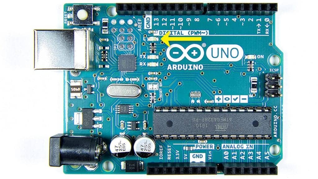
The Arduino has an on-board surface mounted LED that’s hard-wired to digital pin 13:
To get this LED flashing, upload this code to your Arduino:
void setup() {
  pinMode(13, OUTPUT);
}
void loop() {
  digitalWrite(13, HIGH);
  delay(1000);
  digitalWrite(13, LOW);
  delay(1000);
}
The LED should blink on and off at a rate of 1000 milliseconds (1000 milliseconds = 1 second).
How to Connect an External LED to the Arduino
These are the parts you need to connect an external LED to the Arduino:
Follow the wiring diagram below to connect the LED and current limiting resistor to the Arduino:
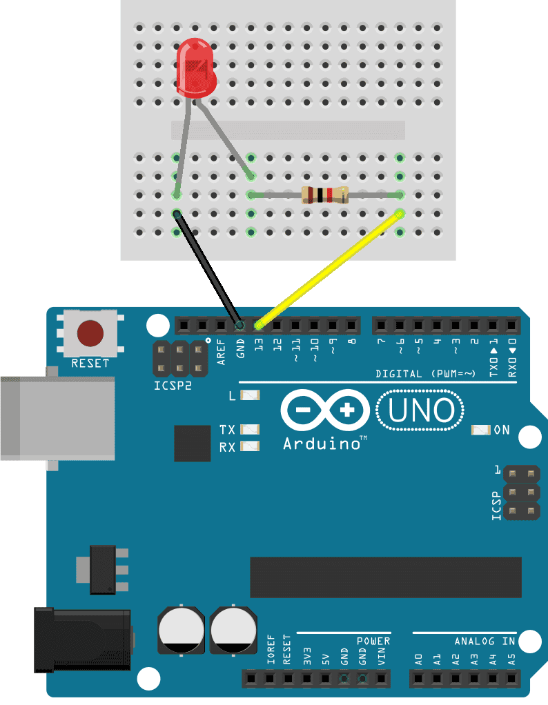
The value of the current limiting resistor should be around 200 to 1K Ohms but the exact value is not critical for this example.
How to Program an LED on the Arduino
Once you have the LED and current limiting resistor connected to your Arduino, upload the code below to the Arduino. This sketch will make the LED turn on for one second, turn off for one second, then repeat:
void setup() {
  pinMode(13, OUTPUT);
}
void loop() {
  digitalWrite(13, HIGH);
  delay(1000);
  digitalWrite(13, LOW);
  delay(1000);
}
Explanation of the Code
First we need to tell the Arduino which pin the LED is connected to and set that pin as an output. For that we use the pinMode() function in the setup() section. The pinMode() function has two arguments – the pin number and the input/output mode:
pinMode(pin, mode);The LED is connected to pin 13 and the pin will be an output pin, so we use this:
pinMode(13, OUTPUT);The code in the loop() section will be executed over and over again in a loop. To turn the LED on, we need to send electric current to it. The digitalWrite() function is used to set the voltage state of a digital pin. It has two arguments – the pin number and the voltage state (high or low):
digitalWrite(pin, value);For the Arduino, a high voltage level is 5 volts and a low voltage level is 0 volts. To turn the LED on, we write a high voltage to pin 13 like this:
digitalWrite(13, HIGH); Next we need to tell the Arduino how long pin 13 should remain high. We do that with the delay() function. The delay() function tells the Arduino to pause before going to the next line of code. The number inside the parentheses is the delay time in milliseconds:
delay(time); We will make the LED blink on and off once every second, so we delay for 1,000 milliseconds:
delay(1000); Now that the LED has been on for one second, we need to turn it off. So we use the digitalWrite() function again, except now we use it to send a low signal to pin 13:
digitalWrite(13, LOW); Then we delay again for 1,000 milliseconds:
delay(1000); You can change how long the LED stays on or off by changing the values in the two delay() functions.
How to Connect Two LEDs to the Arduino
These are the parts you need to connect two LEDs to the Arduino:
Now that we’ve seen how to connect one LED to the Arduino, let’s add another LED to this circuit. We can add a green LED to go with the red LED. Here’s how to connect the circuit:
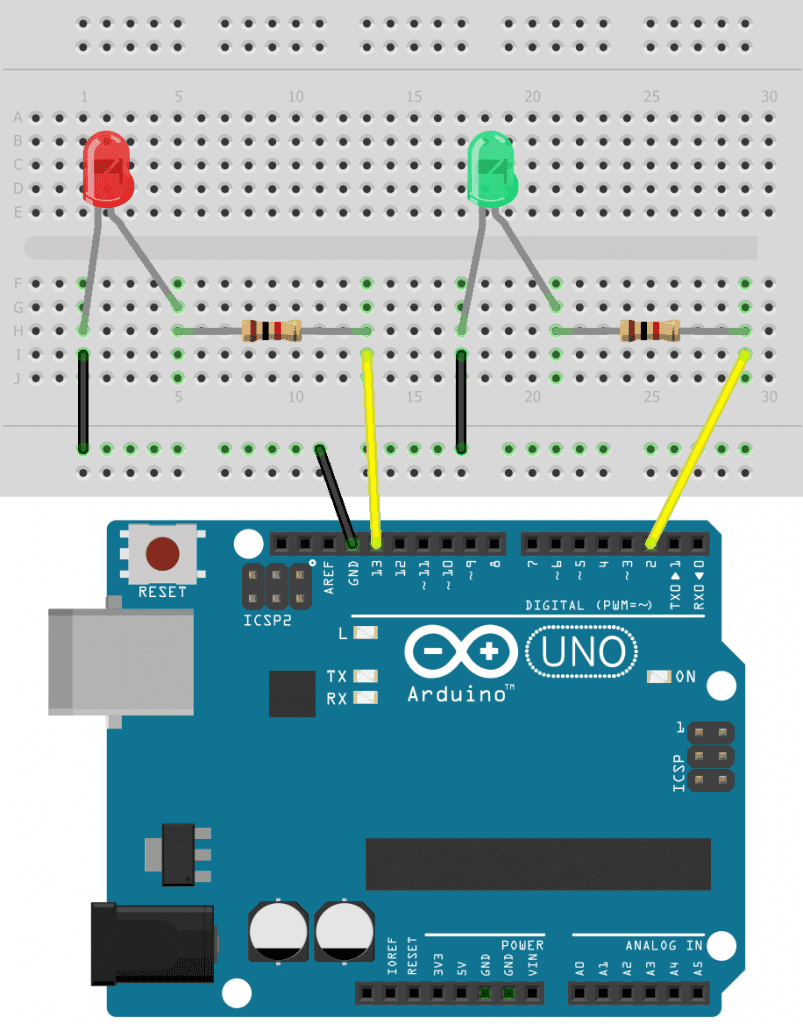
The value of the current limiting resistors can be anything from about 200 Ohms up to about 1K Ohms.
How to Program Two LEDs on the Arduino
To program the two LEDs, we can duplicate the code for a single LED:
int redLED = 13;
int greenLED = 2;

void setup() {
  pinMode(redLED, OUTPUT);
  pinMode(greenLED, OUTPUT);
}

void loop() {
  digitalWrite(redLED, HIGH);
  delay(1000);

  digitalWrite(redLED, LOW);
  delay(1000);

  digitalWrite(greenLED, HIGH);
  delay(1000);

  digitalWrite(greenLED, LOW);
  delay(1000);
}
The only difference here is that we store pin 13 in the redLED variable and pin 2 in the greenLED variable. These variables are used in the pinMode() and digitalWrite() functions instead of the actual pin number.
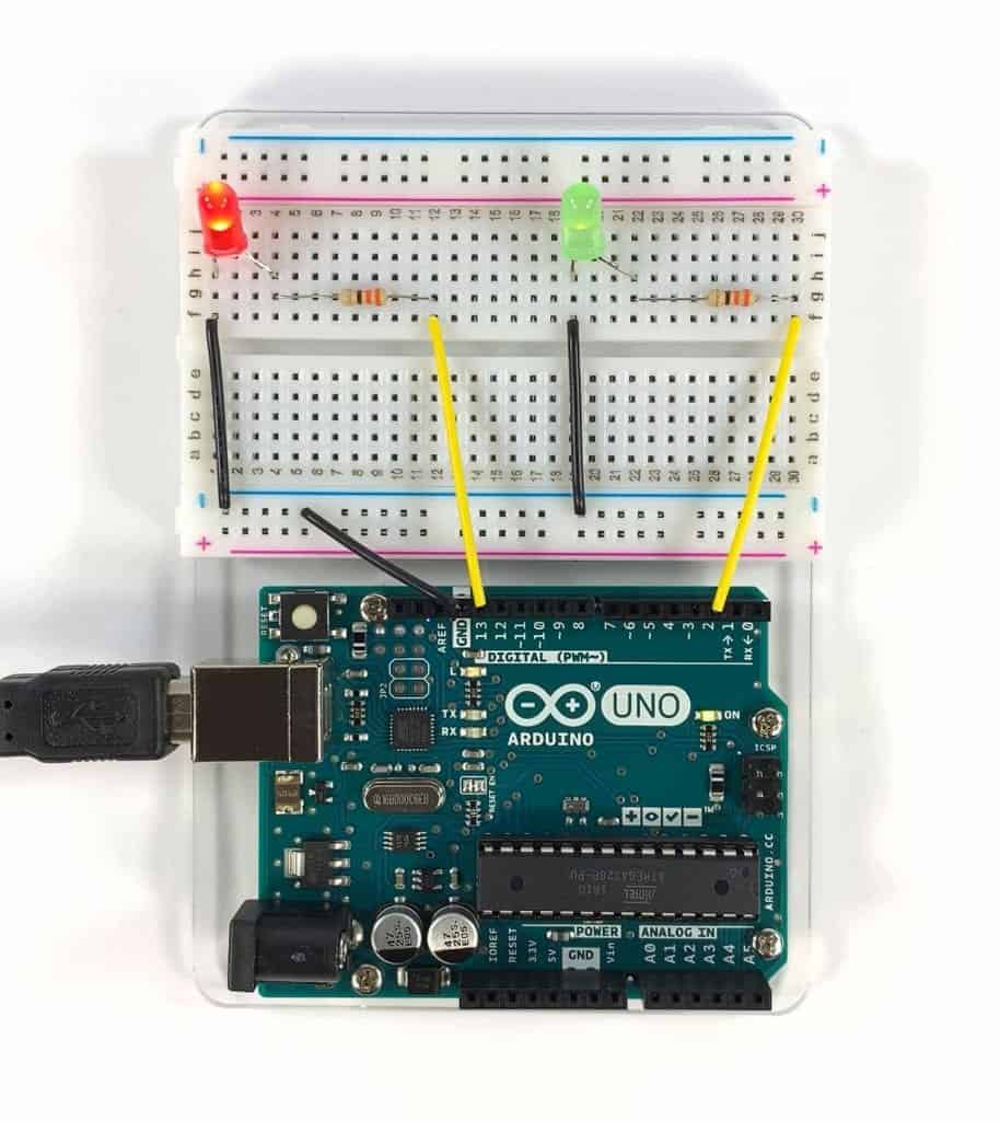
Once you’ve connected the LEDs and uploaded the sketch above, you should see the two LEDs blinking on and off:
Controlling the Arduino’s On-board LED with a Push Button
The Arduino’s general purpose input/output (GPIO) pins can be programmed to act as either an input or an output. As inputs, the GPIO pins can read electrical signals from other devices. As outputs, the GPIO pins can send signals to other devices.
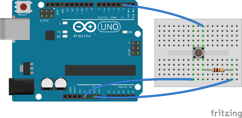
In this project, we’ll demonstrate how to set GPIO pins as inputs or outputs by connecting a push button to the Arduino. The Arduino will listen for a button press at an input GPIO pin. When the button is pressed, the Arduino will send a signal to an output GPIO pin to make the on-board LED turn on.
First, connect a 1K Ohm resistor and a push button to the Arduino like this:
Now, enter this code into the Arduino IDE and upload it to the board:
const int ledPin = 13;
const int inputPin = 2;

void setup(){
  pinMode(ledPin, OUTPUT);
  pinMode(inputPin, INPUT);
}

void loop(){
  int val = digitalRead(inputPin);
  if (val == HIGH){
  digitalWrite(ledPin, HIGH);
  }
  else{
    digitalWrite(ledPin, LOW);
  }
}
The Arduino’s pin 13 LED should light up when the push button is pressed, and turn off when the button is released.
How the Program Works
The pinMode(ledPin, OUTPUT); statement defines pin 13 as an output pin and gives it the name ledPin.
The pinMode(inputPin, INPUT); statement defines pin 2 as an input pin and gives it the name inputPin.
The digitalRead(inputPin) statement tells the Arduino to listen to the inputPin (pin 2) for any signals that might be sent to it.
The if (val == HIGH) statement tells the Arduino to listen for a high signal at the inputPin, which will happen when the push button is pressed. If a high signal is detected, digitalWrite(ledPin, HIGH); will make the Arduino send an output signal to the ledPin (pin 13), making the LED light up.
The else statement tells the Arduino to set the voltage at the ledPin to low if the signal at the inputPin is low. The signal at the inputPin will be low as long as the button is not pressed.
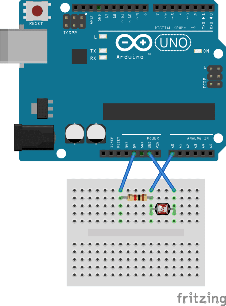
Controlling the Arduino’s LED with a Photoresistor
A photoresistor is a light sensitive resistor that changes resistance depending on how much light hits it. The resistance decreases with more light, and increases with less light.
The Arduino can measure the resistance of the photoresistor in real-time, and use that value to control the blink rate of an LED. Start by connecting a photoresistor and a 1K Ohm resistor to the Arduino like this:
Enter this code into the Arduino IDE and upload it to the Arduino:
const int ledPin = 13;
const int sensorPin = 0;
const int minDuration = 100;
const int maxDuration = 1000;

void setup(){
  pinMode(ledPin, OUTPUT);
}

void loop(){
  int rate = analogRead(sensorPin);
  rate = map(rate, 200, 800, minDuration, maxDuration);
  digitalWrite(ledPin, HIGH);
  delay(rate);
  digitalWrite(ledPin, LOW);
  delay(rate);
}
Now wave your hand over the photoresistor, and you should see that the LED flashes faster when your hand is covering the photoresistor.
How the Program Works
First we define the output pin (pin 13) and input pin (analog pin 0) with these two statements:
const int ledPin = 13;const int sensorPin = 0;
We want long LED flashes when lots of light hits the photoresistor and short LED flashes when no light hits the photoresistor. The minDuration variable defined on line 3 is where we store the minimum flash duration (100 ms). The maxDuration variable defined on the next line is where we define the maximum flash duration (1000 ms).
The int rate = analogRead(sensorPin); statement tells the Arduino to read the resistance of the photoresistor at the sensorPin (pin 0) and to store the detected value in a variable called rate.
The rate = map(rate, 200, 800, minDuration, maxDuration); statement tells the Arduino to convert the raw ADC values (0-1023) from the photoresistor to values between 200 to 800, then map those values to numbers between the minDuration and maxDuration. This way, all ADC values from 0 to 1023 will be mapped to duration values between 100 ms and 1000 ms.
The delay(rate) functions in the void loop() section first tell the Arduino to send a high signal to the ledPin for the duration of the rate value. Then a low signal is sent to the ledPin for the duration of the rate value. This produces the on/off flashing effect.
Now that you’ve seen how to control LEDs with the Arduino, be sure to check out our other tutorials connecting an LCD, setting up an ultrasonic range finder, or using a humidity and temperature sensor with the Arduino.
Feel free to leave a comment below if you have any questions or have trouble getting these projects to work. And be sure to subscribe! We send out an email each time we publish a new tutorial…


I am quite new at arduino. I have a arduino uno board. When I connect it to my computer and upload the code at the under the page it says:
“Cannot run program “{runtime.tools.avr-gcc.path}\bin\avr-g++” (in directory “.”): CreateProcess error=2, System cannot find the file.”
Whats I am doin wrong?
hi
first disconnect your arduino and verifi the code.
then go to the tools menu and go to ports it will show a unique port for arduino select that and upload the coad
it will get uploaded
even i got the same problem i did this and it got solved..
make sure you’ve selected the correct board and port under “tools.” it should be “arduino uno” and “usb” respectively.
You mean on/off state?
Easy and straightforward yes, but would it not be better practice to teach new users not to use ‘del… https://t.co/wMlEyX5YCx
curious to see if the code for this could be fed by way of an xml file or something, to control when the light is on and off.
please , how can I change the power of led ( I want to change its power highest or lowest while the led is on )
without using a manual method .
I want automatic way for this .
by programming .
I guess you need to deal with “analog pins” of Arduino.
If you copy paste the code into arduino ide it refuses to work. Why is there not a program that simply lets you do what you want in a sensible way? Let met just set the pin I want as an led and let me tell it what to do. I really feel like I threw money away with this.
Bro what error do you get on the IDE?
I haven’t been trying to pass the class that uses this on Coursera. I don’t even know about that.
Have you checked out the Tinker sight. I did some nice models on my table tonight with that.
Don’t listen to Mr. Perhaps. You need to understand that the internal LED on the Arduino Uno is on pin 13 on the digital side as shown in the article, also you need to make sure you include (using the include function) all the right packages to run this Arduino code. The code is there, circuit basics did it for you because you want to play pubg and not read the datasheet, but you’ve gotta make sure you include the right packages in the C program.
Hi. How can i use alot of leds using a breadboard and considering them as one big led connect it with just a single pin of the breadboard for the output? and power it with an external source?
Is there a way to make a light flicker on then off during a note? For reference, one of my lines of code goes like this:
digitalWrite(6,LOW);
digitalWrite(5,HIGH);
digitalWrite(5,LOW);
Serial.print(“ne, “);
tone(9, NOTE_B4); delay(1400);
I’m trying to get pin 5 to flicker on during the note, then turn off while it’s still playing. The issue is that the pin 5 LED doesn’t light up at all, and I can’t get it to work. Please help.
david
hello , i want to blinking led with 2hz 3hz 4hz 5hz 25hz 40hz with arduino uno but what is delay and calculation ?