
In this tutorial, I’ll show you how to build a great sounding audio amplifier with the LM386 Low Voltage Audio Power Amplifier. I built about a dozen different audio amplifier circuits with the LM386 but most of them had way too much noise, popping, and other interference. Finally I found one that sounds great, so I’m going to show you how to build it.

It’s not a “minimal components” audio amplifier. I added a bunch of extra capacitors to reduce the noise, and I added a bass boost control as well to make it sound even better. But before we start building, it might be helpful to get a little background information first…
LM386 Basics
The LM386 is quite a versatile chip. Only a couple resistors and capacitors are needed to make a working audio amplifier. The chip has options for gain control and bass boost, and it can also be turned into an oscillator capable of outputting sine waves or square waves.
There are three varieties of the LM386, each with different output power ratings:
- LM386N-1: 0.325 Watts
- LM386N-3: 0.700 Watts
- LM386N-4: 1.00 Watts
The actual output power you get will depend on your supply voltage and speaker impedance. The datasheet has graphs that will tell you. I used a 9V battery for the power supply and it works great, but you can go down to 4V or up to 12V.
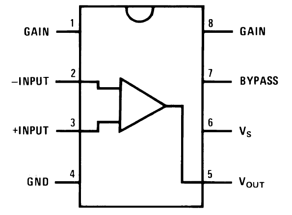
The pinout is shown in the diagram below:
Download the datasheet for more information about the output power, distortion characteristics, and minimum/maximum ratings:
The LM386 is a type of operational amplifier (Op-Amp). Operational amplifiers have a basic task. They take an input potential (voltage) and produce an output potential that’s tens, hundreds, or thousands of times the magnitude of the input potential. In an amplifier circuit, the LM386 takes an audio input signal and increases its potential anywhere from 20 to 200 times. That amplification is what’s known as the voltage gain.
Gain vs Volume
After you build this amp and play with the volume and gain controls, you’ll notice that both appear to raise or lower the intensity of sound coming out of the speaker. So what’s the difference then? Gain is the amplification of the input potential and is a characteristic of the amplifier. Volume lets you adjust the sound level within the range of amplification set by the gain. Gain sets the range of possible volume levels. For example, if your gain is set to 20, the range of volume is 0 to 20. If your gain is set to 200, the range of volume is 0 to 200.
Gain control can be achieved by connecting a 10 μF capacitor between pins 1 and 8 . Without a capacitor between pins 1 and 8, the gain will be set to 20. With the 10 μF capacitor, the gain will be set to 200. The gain can be changed to any value between 20 and 200 by placing a resistor (or potentiometer) in series with the capacitor.
A Minimal LM386 Audio Amplifier
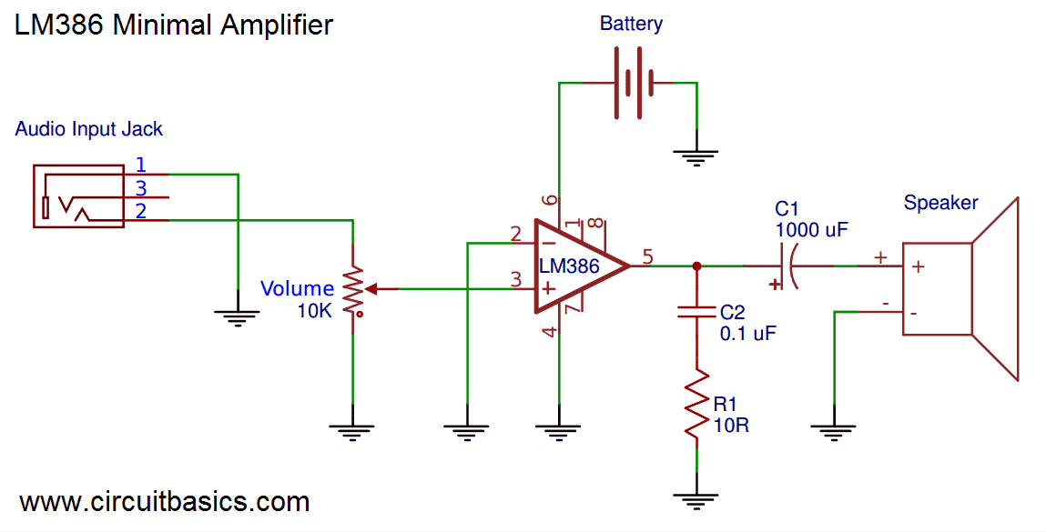
Now that we have a little background information on the LM386, let’s start by building a bare bones LM386 amplifier with the minimum amount of components needed to make it work. That way you can compare it to the better sounding one we’ll build later on.
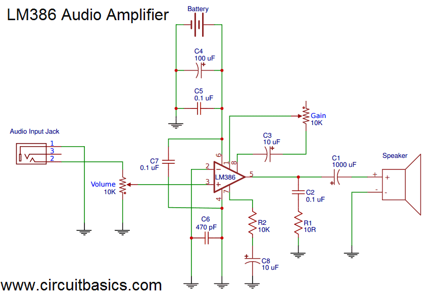
Here’s the schematic:
Here’s how to wire it if you’re using a breadboard:
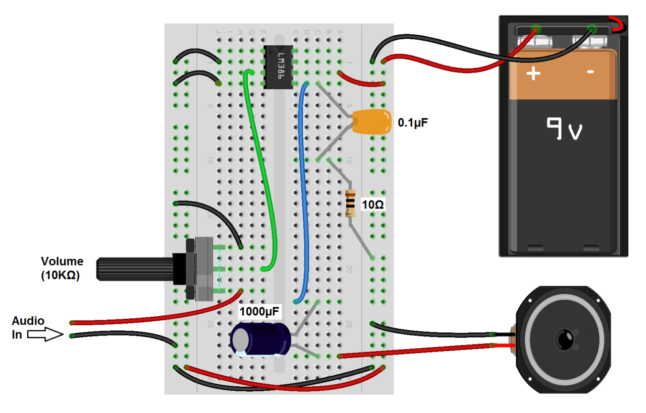
In the wiring diagram above, the audio input ground flows through the same path as the audio output ground. The output ground is “noisy” and will cause distortion in the input signal if it’s wired this way. The audio input ground is sensitive to any interference and any noise picked up will get amplified through the amplifier.
Make it a goal to keep the input ground separate from other ground paths as much as possible. For example, you can connect the grounds for the power supply, input, and output directly to the ground pin (pin 4) of the LM386 like this:
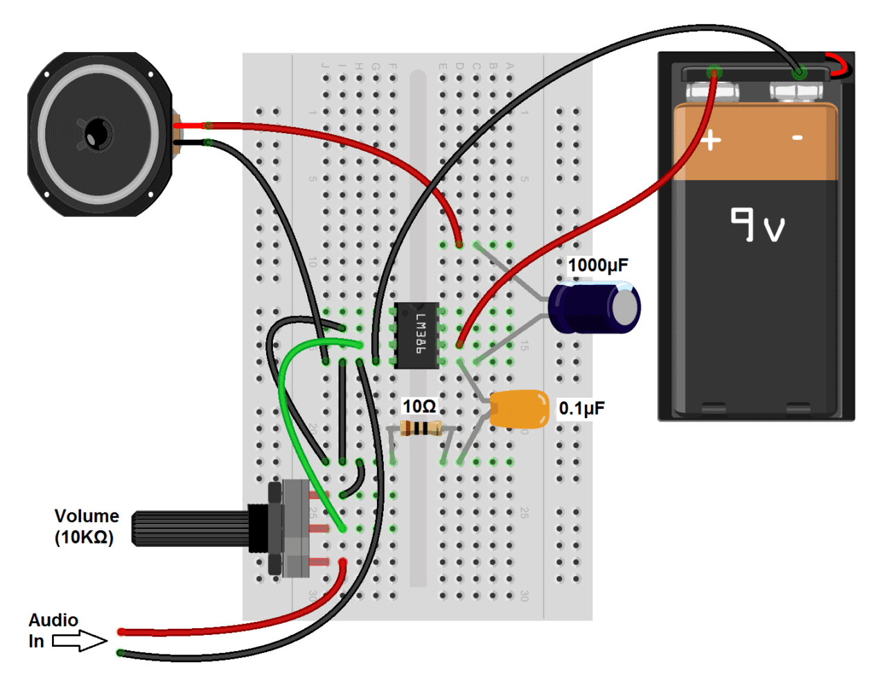
This will reduce the distance the input ground flows through the output ground. Connecting it like this should sound better than the first circuit, but you”ll probably still notice some noise, static and popping. We’ll fix that in the next circuit by adding decoupling capacitors and a couple RC filters.
A Great Sounding LM386 Audio Amplifier
Now that you’ve seen the bare minimum of what it takes to make an audio amplifier with the LM386, lets build a higher fidelity version with an adjustable gain control.
Note: Most of the component values in this circuit aren’t critical. If you don’t have a particular value, try substituting something close and it will probably work.
Here’s the schematic:
Several things in this circuit make it sound better:
- A 470 pF capacitor between the positive input signal and ground, which filters radio interference picked up by the audio input wires.
- 100 μF and 0.1 μF capacitors between the positive and negative power rails to decouple the power supply. The 100 μF capacitor will filter low frequency noise while the 0.1 μF capacitor will filter high frequency noise.
- A 0.1 μF capacitor between pins 4 and 6, for additional decoupling of the power supply to the chip.
- A 10K Ohm resistor and a 10 μF capacitor in series between pin 7 and ground to decouple the audio input signal.
This diagram will show you how to connect everything if you’re using a breadboard:
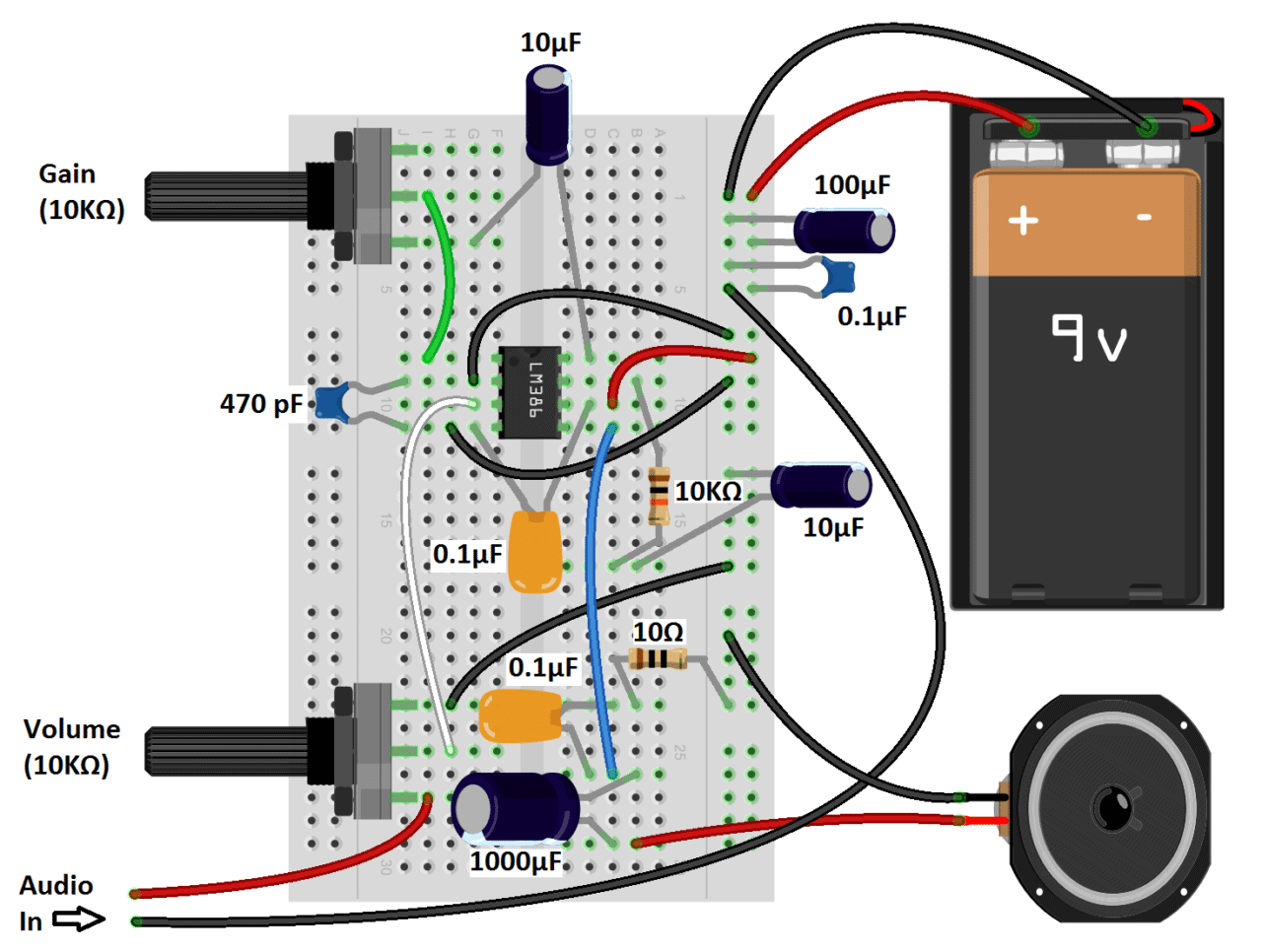
One thing to keep in mind when you’re wiring any audio amplifier is that the cleanest sound will result from keeping all wire connections and components as close to the chip as possible. Keeping the wires as short as possible will also help.
The LM386 Audio Amplifier with Bass Boost
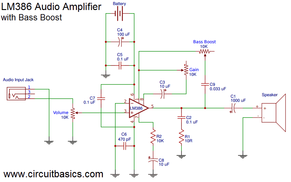
A cool feature of the LM386 is the option to add an adjustable bass boost to the amplifier. You’ll probably find that this is the best sounding circuit. The bass boost is basically just a low pass filter, and it removes most of the noise not taken out by the decoupling capacitors. All you need for the bass boost circuit is a 0.033 μF capacitor and a 10K Ohm potentiometer in series between pins 1 and 5:
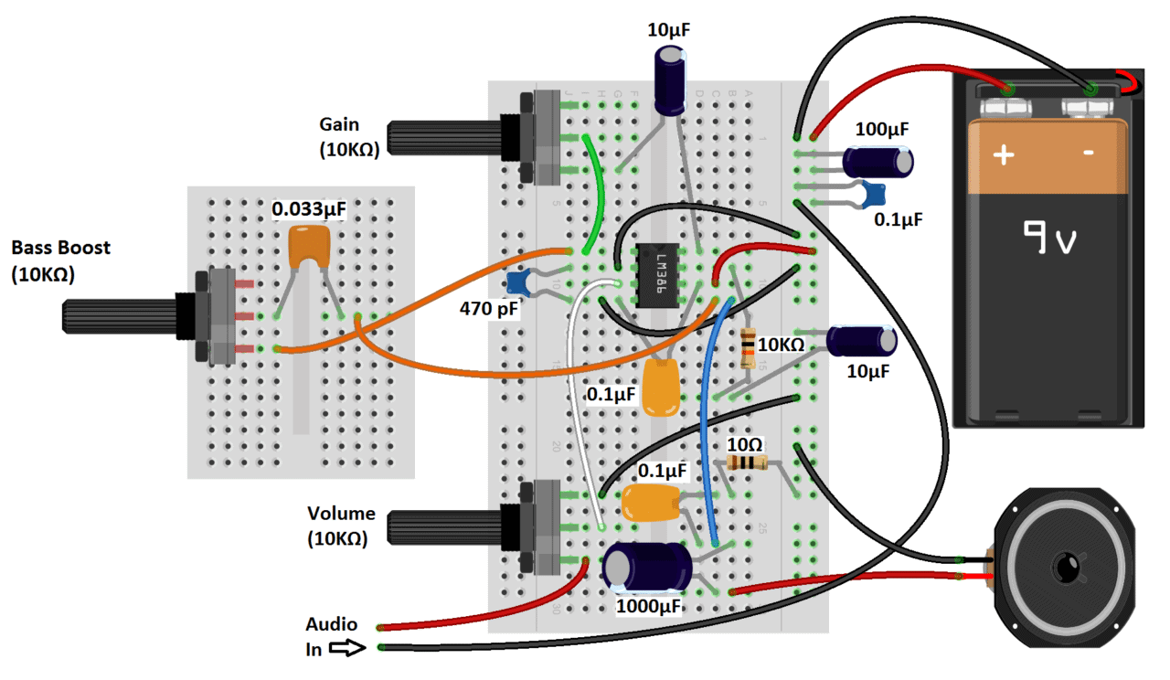
Here’s the wiring diagram:
An easy way to connect the audio input in these circuits is by cutting the 3.5 mm audio jack from an old set of headphones and wiring it to breadboard pins. Check out this article, How to Hack a Headphone Jack to see how to do this with some common types of headphones.
Here’s the video version of this tutorial if you want to watch me build the amps and listen to them:
Thanks for reading! Hope you had fun experimenting with these amps as much as I did. If you’re ready to build some even better sounding and more powerful amps, we have tutorials on a few others:
- Hi-Fi 40 Watt stereo LM3886 amplifier
- 25 Watt stereo TDA2050 amplifier
- 12 Watt stereo and bridged mono TDA2003 amplifiers
The LM3886 is by far the best sounding amplifier, but it’s a fairly involved project. If you’re just starting to build audio amplifiers, I’d recommend working your way up to it by starting with the TDA2003, then moving up to the TDA2050.
Be sure to subscribe to keep updated on our posts as soon as they are published. And feel free to leave a comment if you have any questions or need help with anything in this article.


Great little article, thanks. I’ll try that some day. I didn’t quite get which one of the three LM386 models you’re using? BTW the number 386 sure do bring a lot of old memories back. My first pc, 80386, 40mhz with 4mb ram. Some how I miss old dos, in some ways it was less complicated back then.
Get a Linux distro, you can do pretty much everything from the command line.
Thanks yaboc, glad you liked it. I used the LM386N-1, but the setup would be the same for each model, the main difference being the power output.
The 470p on the schematic is shorted out, both ends to ground. Think it’s supposed to connect to pin3 not pin2
Actually, you want caps at both pins 2 and 3, but for different purposes. A 47 pf cap at pin 3 to ground will accomplish the stated interference reduction purpose, but a cap between pin 2 and ground *instead** of the customary short of pin 2 to ground is important. Such a capacitor serves as an * AC * short to ground in place of the commonly used DC short to ground which, by shorting out the 50K internal biasing resistor that’s right at the Inverting input (pin 2) , would create a bias imbalance between the inverting and non inverting halves of the chip, in turn causing an imbalanced clipping to begin to occur at a volume that is slightly less than that at which a balanced clipping would begin to occur had both sides been equally biased. Using an AC short to ground thru a 470pf cap (in place of a DC short to ground that shorts out pin 2’s internal biasing resistor) can prevent this, but leaving the original short at pin 2 in place defeats the purpose of adding it. In the schematic shown, disconnect the ground connection on the pin 2 side of the cap, so that the cap can do its job. You’ll then be able to get a slightly greater volume before clipping occurs.
If you have a scope, try this:
With the 470pf cap at pin 2 shorted (to force pin 2 to go directly to ground), input a sine wave and watch it on the scope as you slowly increase the volume. At some point you’ll see clipping begin to occur on of the top half (or bottom half, depending on how your scope is connected) of the sine wave, but not (yet) on the other half. Now, remove the short you’d placed across the 470 pf cap at pin 2 so that pin 2 now goes to ground only thru the cap. Lo and behold, the one sided clipping has disappeared, and both peaks of the wave are rounded, as they should be!
Now, as you increase the volume, clipping will still occur, but when it does it will be symettrical and will begin at a slightly higher volume. than that at which the one sided clipping had previ ouslyoccured.
.IIn short, this cap gives you slightly more power out of the chip before clipping distortion begins.
Thank you for clarifying the doubt with caps on pint 2 and 3. “but a cap between pin 2 and ground *instead** of the customary short of pin 2 to ground is important. Such a capacitor serves as an * AC * short to ground in place of the commonly used DC short to ground ”
I think you should correct the diagram to reflect this change.
bitteleeee divaaa
Dear Sir,
What will be the maximum power output from this configuration? can i use this same circuit to power a Two 6 W / 4 Ohms Speaker ?
Hi I was wondering about this amp are those mono amps?
and also due to you used the Lm386N-1 will this IC work with 16-32 ohm speakers?
This circuit not working at all
Hi Sanjeev, double check to make sure everything is connected properly, and the polarity of the electrolytic capacitors are correct…
This tutorial is AWESOME. I have built some LM386 projects before but this one has the greatest versatility of the ones I’ve seen. I’m gonna build a preamp for my microphone using this circuit, thank you!
could you please list all the components that your used for the LM386 Audio Amplifier – And whats did you use to connect you mobile phone from.
Sir you can use a 3.5 MM AUX Cable which also known as auxiliary cable which is a valance in the market all you need to do is just to assemble the auxiliary cable as per instructions given in the auxiliary cable box and connect it to the circuit through the headphone jack of the cell phone or any other device
Hi Sipan, to connect the amp to my iPhone, I cut into an old pair of headphones:
https://circuitbasics.com/Staging/how-to-hack-a-headphone-jack/
http://i2.wp.com/www.circuitbasics.com/wp-content/uploads/2015/04/LM386-Audio-amplifier-with-Bass-Boost-NEW-2.png
Very informative!,im building a project like this which started yeaterday and i just stumble here looking for some infos about LM 386.,a much elaborated step by step video has finally come,compare to some of those who just showed off their build but not showing how they do it.Thank you for sharing!
Hi, thanks for nice tutorial. I have a project about getting signals from input (such as microphone or mp3 player), amplify it and connect to Arduino Uno’s Analog input and then record amplified as WAV file into SD card. it will be a portable device, therefore it should work with 3.7V Li-PO battery. So my question is LM386 can work with 3.7 V? if it’s not then which kind of amplify IC should I use ?
As Tuck said, you could use a small boost convertor. You can always take one from a basic portable power bank, as those commonly use LiPo batteries. You could also look into the PAM2401 for simple boost conversion, or also get the MCP73831 for constant current and temperature regulated charge control. You can also add some protection diodes and daisy chain your batteries together.
You could use a small boost converter.
Hi Onur, according to the datasheet, the LM386N-1 has the lowest minimum voltage requirement, which is 4 volts… So a 3.7V Li-Po battery will be just under the minimum. You might want to look at the LM4804 or the TPA721
I made an schematic for this , and i don’t know if it is ok
link to it: https://mega.co.nz/#!e84FWAyT!Wh9r_4AwMzvefpHALSXMpVzr38NHMoI_iCySEYpTUSA
so if you could check it, please , and if i have any mistakes you can correct them, it is made in proteus
can you send me i can`t open it plz send me at qasim.muhammad2012@gmail.com
please send me the file i cant open it thanks.
jeffersonyagdulas@yahoo.com
Please send me the schematic diagram .
Rayjat51@gmail.com
Hi, I can’t see the schematic from the link. Will you be kind enough to email it to me? riotbmx (@) gmail dot com
I have a question about that 0.1uf capacitor , is that polarized or non polarized? And what are the voltages of capacitor that you used? Thanks . i’m newbie.
The circuit operates at 9V, so any capacitor voltage rating above about 16V will work fine. The 0.1 uF capacitors can be ceramic disc, but polypropylene film types will sound much better. Both are non-polarized.
I want to know the voltages too of each capacitor :)
Tnx
That capacitor can go either way…no polarity…if the diagram has a capacitor, with a curve in it, it has to be put in the right way…or has polarity..
0.1 uF are ceramic disc capacitor. So polarity doesn’t matter.
Actually, that is a film capacitor and film capacitors do have a polarity, even if they are “non polarized”. The reason is that there is always an outer shield, with film caps. In other words, there are two foils that are rolled together and the foil that ends up on the outside should be connected to the negative, because that relatively large area of metal foil picks up interference, which results in noise in an amp. You need an oscilloscope to measure this. Go to YouTube and search for “are non polarized capacitors polarized” and you will see.
Thank you so much. So well documented and illustrated compared to other tutorials out there. Much appreciated.
As an old Pensioner (72) just starting out in electronics I have completed my(your) first amplifier.
Thanks for an exceptionally clear tutorial. I will now attempt the second version.
As a request, would you not like to attempt a oscilloscope using an arduino uno with the same clear instructions
Thanks again
Roy
May I know what are the voltage of all the capacitor used?
Thanks
I usually just double the voltage for the circuit….9 volt supply would be 18 volt capacitors or more..
Good day! I just want to ask if you can send me a copy of the schematics because im not used to bread boards (which is I am really ashamed of, LOL). I want to rebuild the 1st circuit with the pin 1 connected on the pin 8. I’m really interested with this project because I’ll send it as a gift for my girlfriend. I hope you’ll be reading this soon, Thanks chief! And BTW, nice work! I’ll save this site for future projects :)
my god what a lovely loud sound every thing o.k. but to pin 1 and 8 conected with a jumper with out any capacitors
my friend shouted that it is not a publicmeeting.Really the gain is very high superb earlier i was thinking to increase the volume .After seeing this site i wondered LM 386N-4 is a great chip. Also u can try with LM386 M1-DIP8 (not sop8)
Is there any cheap and good quality stereo amplifier for headphones?
Hi Alex, this amp works great for headphones… Since the diagrams in the post are mono amps, all you need to do is build two amps, one for the right channel and one for the left channel. You’ll also want to get a “dual-gang” potentiometer for the volume control so both channel volumes are adjusted at the same level.
Dear Alex
the same circuit u can use by connecting pin 1 and 8 with jumper works well with 3.7 v battery .Thanks
to circuit basics.I tried even there is clear voice.
thanking once again to Circuit basics
forgot to tell just avoid using treble and boss use only 10k pot.
Thanks for noticing! I’ll look into this. Sorry for the confusion…
What was the impedance of the speaker you used? I would like to replicate this circuit.
I used an 8 ohm speaker, but anything from 4 to 16 ohms will work. For the capacitors, I’d use anything above 16V. Keep in mind though, higher voltage rated capacitors are larger and more expensive…
I make this circuit..but it is not working..plz send me new update
I used a 4 ohm speaker
Do you need a picture of the circuit? Oh btw, i was trying to make the minimal lm386 aduio amplifier
I can try that, but i doubt it will work though, becos there isn’t any sound coming out of the speaker in the first place. Cant seem to figure out what is wrong cos i followed the diagram exactly without success
You need to do the one that is 15 watts so we can really jam out.
Check out our tutorial on the TDA2003, it has about 12 watts output power:
https://circuitbasics.com/Staging/complete-guide-to-build-a-10w-amplifier-with-the-tda2003/
How can I build a 7.1 home speaker at home
Is the ic LM 386n will be the same kind or what. I have made the previous works fine.
Yes a common ground in audio is not the way to go
Could you post a link to the video? I have made this circuit, and it works pretty good, just can’t crank it too high due to the distortion( can only go to about 3/4 throttle, but that ain’t bad). My problem is that when I try to mount it in its intended case (Altoids tin) the signal goes out and I get no sound. I have tried to insulate everything but it doesn’t work. I may just try to use a plastic enclosure, but I put a lot of effort into setting up the Altoids tin just right.
https://www.youtube.com/watch?v=lBGE5lwbruE
Thanks. Was real informative and will probably help solve my problem.
hi! thanks!, great page!
i’m workin on a diy ebow project, which is basically an amplifier just like this, do you know it?
I haven’t heard of the ebow, but I’m Googling it now!
queston: do this amplifier have enough gain to be used to hear the guitar magnetic pickup’s output with earphones? a sort of personal monitor? thanks!
Yes it will
do you have the schematic for the great sounding lm386 audio amplifier?
Hi Roi, unfortunately I don’t have any other schematics for this amp. The only diagrams I have are already included in the article
can you tell me the voltage of the capacitors thanks
0-16 volts
16v
Thanks for nice explaination. I am interested in recycling my old notebook speakers 2watts each to make a usb driven amplifier with 2.7 – 5v input volt. Please let me know what modifications I need to apply to your circuit.
I think you should be good to go without any mods to the circuit. Have fun!
Can you please include the circuit digram bacauase I’m a beginner and I need it for a project in collage
The only circuit diagrams I have are already included in the article.
I have tried others circuit regariding this LM386 and this is the best circuit i can say but just wondering can i use a 3.6ohms SUbwoofer instead of the 8ohm speaker?
Thanks! Yes, you can use a 3.6 Ohm sub instead… You can use any speaker really, but bigger units will need higher wattage pre amps to amplify the audio.
can you please mail me or whatsapp me a pcb design for this circuit?
Mail: iamjiths@gmail.com
whatsapp: +918891100770
Sorry, unfortunately I don’t have a PCB diagram for this circuit.
how can i connect a mic and use it for recording ???
To use it as a mic pre amp, you would connect your mic to the input of the amp, then instead of having a speaker connected to the output, you would connect the output to your recording device.
pls how can i increase the wattage of d circuit to 16watt and 8ohms i will add you on whatsapp +2347039130281 tanks alot for the post
Hi hybee, the LM386 won’t output 16 watts. For that you would need to build a tda2003 or tda2050 amp. Check out these articles:
https://circuitbasics.com/Staging/complete-guide-to-build-a-10w-amplifier-with-the-tda2003/
https://circuitbasics.com/Staging/tda2050-diy-amplifier-build-guide/
Hey, um this really is one of the best diagram i was just wandering that is this an 8 ohm speaker used?
Thanks! The speaker I’m using is 8 Ohms
What’s the difference between the two potentiometers? I know one controls the volume and the other controls the gain, but doesn’t changing the gain also simply change the amount/volume of the output?
This is actually explained in the article.
Hi, I am building a project similar to this, however it will feature four of these units(four LM386’s with four speakers) in parallel. The idea is that they share the same audio signal but have a different volume, controlled by a multiple channel digital potentiometer (AD5204/6) through an Arduino. Any suggestions on whether the audio signal can just be parallel(or would I need separate audio signals?) and the 4 LM386’s connected to the same power source? Thanks in advance for helping already getting far with building it.
Hi, I am doing an audio amplifier but with 3 outputs instead of single output…so what should i add to make it work
Hi, In one part of the circuit there are two decoupling caps connecting the positive rail to ground. One of those caps is a 0.1 μF. Then there is a 0.1 μF cap from pin 4 (which is also connected to ground) to pin 6 (which is also connected to positive rail). I know very little about electronics, but to me it seems that the 0.1 μF cap connecting pins 4 and 6 is the same thing as connecting a cap between the positive and negative rails. Is it a mistake, or should there be a total of three caps connecting the positive rail to ground, of which two caps are 0.1 μF? Thanks…
The idea is to put another capacitor as close as possible to pins 4 and 6 to maximize the decoupling. There should be three caps connecting the positive rail to ground. The 100 uF and 0.1 uF decouple the power supply for the entire circuit, while the cap connecting pins 4 and 6 are to add even more decoupling for the chips power pin.
This was my first amp , my first real circuit, and I did it with your video ! I’ve tried to make other more powerful amps to get better volume but I have had poor luck with other more complex IC’s, do you have other tutorials for other amps?
I was wondering If could get a schematic of the 2nd circuit with the volume and the gain at my email hjay795@gmail.com thank you again I’m trying to build it but I’m having some difficulties
Thanks from Colombia!
can you plzz give me the exact specifications of capaciter’s volt and speaker’s ohm and watt
It’s an 8 Ohm speaker, not sure about the wattage though.
did u ever find out the ohm and watt? i think 4 or 8ohm but not sur eon the wattage
Sir, thank you for the great tutorial it really helps a lot
can you give us an schematic diagram?
excellent write up and video, well done, I will do this, I have minimal soldering skill but schematic challenged, will do this for stereo 2 channel, will have to duplicate pretty much everything …,
A Good Job of explaining this. I am continually surprised since I grew up with Transistors and IC’s that people don’t know this stuff.
I started with the LM707 then the LM741 op amps so I am always pleased to see someone trying to make this simple for the new folks!
It should be required to do some things with this before graduating to a IC class D amp!
Is is possible to use more than 9v for example 12v with the two latter circuits just as is or is there anything that needs to be changed?
The LM386 voltage rating is from 4V to 12V, so you can use 12V without changing anything.
Hi
I don’t have 470uF capacitor. what can I use instead ?
thanks
Do you mean the 470 pF capacitor? You can use another value for all of the capacitors, but they should around the same value
Can you post the Schematics for these Circuits?
Sure, I just added schematics for each circuit…
circuit did’nt work…please help
CAN ANYONE GUIDE ME HOW I CAN CONNECT TWO SPEAKERS IN THIS CIRCUIT
You can connect two speakers in parallel. So the two negative wires would connect to the negative rail, and the two positive wires would connect to the negative side of the 1000 uF capacitor. This will still be a mono amp though.
If you want to make a stereo amp, you’ll need to build two amps, and connect one amp to the right channel and one amp to the left channel.
It would be better to connect them in series than in parallel. The LM386 power efficiency drops markedly (and the chip heats up more quickly) as its load impedance is reduced. One engineer on the web has reported (and used graphs from the LM386 data sheet to help explain why) that he got more effective use of the chip with a 4 ohm resistor in series with a 4 ohm speaker than by using the same speaker alone by itself.
just a very good article … thanks
good one
how do you know which pins are which on the 386? in other words, which way is up? thanks for this!
There should be a small notch on the top of the chip that looks like a half circle. The notch is on the side that goes up, so pin 1 will be on the left of the notch, and pin 8 will be on the right.
how can i solve that circuit? .pls pm me
Hi,
When you added the bass bost control, can you add a speaker that gives bass only, (something much more like a sub-woofer)???
For that I think you would be better of building a dedicated subwoofer amplifier, or using a tone control circuit. There are better chips and circuits to use than the LM386 for that purpose.
Hi,
I didn’t understand the input taking from mobile using audio jack?
Can you please help in that input portion?
I cut into an old pair of headphones for the 3.5mm input plug. Check out this article for more info: https://circuitbasics.com/Staging/how-to-hack-a-headphone-jack/
Thanks for this article, i was looking for something like this!
I converted my old car stereo to use bluetooth, by bridging the bluetooth module’s audio output into the chip directly, into the input pins (Philips TEA0675T, if it helps). However, i’m getting a considerable volume difference from the radio (the bluetooth device is much lower) and i’d like to create an amplifier as yours.
Couple of questions: The potentiometers are not required, i suppose, if i am ok with having full volume all the time;
Also, what sort of regulator do you think i’d need to run the system at 12v instead of 9v?
Thanks in advance!
Hi Bruno, you can run the LM386 at 12V without a regulator. Also, it sounds like you would be using it similar to a “power amp” where the pre amp controls the volume. In that case, sure, you don’t need the volume potentiometer. Just run the positive input straight into pin 3…
Have you looked into the TDA2003? That amp was designed for car audio use, so it might be a better choice for you project…
https://circuitbasics.com/Staging/complete-guide-to-build-a-10w-amplifier-with-the-tda2003/
Awesome exercise. Mine was working right away and really surprised at the clarity. At the moment, mine is in-between the basic “Minimal” and the “Great Sounding” versions until more parts arrive. Really fun to be driving powerless 8ohm speakers from the Android phone or PC.
Can this circuit be used to increase an audiot input from a 100 Hz up to 50 KHz? And a really helpful video btw!
can this circuit work with a bigger speaker ??
and if I connect a headphone instead of the speaker will it work ?
I built a stereo version of this using 2 .375w LM386 Ic’s.. I left out the gain control (set at 20) and no bass boost – I use equalizer of MP3 player for that- wow! It drives a pair of 8Ohm Onkyo home theater speakers with room filling sound. Next one I build will be with the 1 watt output LM386. Thanks!
That was a mistake, the diagrams have been updated now
is this working right now? http://i2.wp.com/www.circuitbasics.com/wp-content/uploads/2015/04/LM386-Audio-amplifier-with-Bass-Boost-NEW-2.png
i am planning to make this one
Hi please could u email me the updated ones as in the video on one of the capacitors u didn’t say what it was you just said put a capacitor here. i need it for a school project, thanks! (im doing the bass adjustable one)
Could u please send me an updated schematic? It would be nice if you could post it and make it available to everyone. What is the range of the (…-1 chip) ac voltage output? I need to break-in my new subs.
I recently discovered this as well… The grounds for the input, output and power should run separately from the ground pin of the chip to reduce interference. I have updated all of the diagrams so that they all run from pin 4. It does sound a bit better.
You’re right, thanks for pointing that out. I just updated the images to show the positive side of the cap leading to pin 5. By the way, I’m using polarized tantalum capacitors, but non-polarized ceramic caps will work too.
my dear sir how find the 0.1 uf positive and negative am a novice but trying under guidence only
The 0.1 uf doesnt have any polarity…… In other words you can use it in any direction you want
dear Circuit basics,
I realised that any capacitor connected to direct IC pins should possitve + am i right sir
other wise they are not working,
S Prakash rao
Dear sir
Resenltly i purchased the Arduino Duo board for INR 1200 but when i conected to my laptop asked me to download soft ware and i down loaded. It is asking me to write a programme. Do i need to learn C programme.
so how to learn c programme from basics. Do i spend money for that. I am at your mercy sir if any amount to be
paid i am ready to pay
I am your fan. By seeing articles only i merged the 1& 8 pins of LM386 which turned in to amazing sound. since then you happened to be my 1 st choice.
sorry for disturbing you sir.
S Prakash Rao
98480 53185
India
No you dont need to learn c language…. Though its better if you do…… But if you search in Google with the name of the project you will find the script…… Just copy and paste it
very beautifully explained
Thank you this helps so much, im wondering if there was any way i can minimize the input voltage down to a 3.7v dc just to make it portable enough to charge and carry around, thanx,
The minimum voltage rating is 4V, so it might not work. If your voltage is lower than the minimum, the power output will be very low and the audio will probably distort. You may want to look at the LM4804 or TPA721 for 3.7V power
Thank you so much for that tutorial
it’s very fun (and instructive) to see how the sound get better and better with every new circuit
the best sound i have got with this chip, i have tried various circuit on the web and this one is the best sounding one.
Thank You :)
yes that´s how to do it
What is the output of the circuit?
With 9V and an 8 ohm speaker the power is 500 to 750 mW
Excellent article dude!!! You really did a great job here…I actually wanted to construct an external amplifier to connect to my Pc and Phone as we know how lousy and low the Audio output are. Your design and description has really helped me to design one very easily and really working well. Thanks alot!!!
Where is the schmetic diagram?
good production. But you specify the voltage of each capacitor
can we use a electret microphone for audio in?
I have 2 questions…. 1. Can I use 100k pot ?????
And 2. I cant find the 0.1 uf capacitor……. Will this one do??? https://www.techshopbd.com/product-categories/capacitor/926/0-1uf-275v-capacitor-techshop-bangladesh
in answer to your first question yes but it will be harder to use as most of the turning will do nothing
I have a suggestion….. If you want to lessen the jumper wires, use stapler pins for the short connections….. They work just as well and are better than a handfull of jumper wires…
please can you tell me that can i use any other value of capacitor instead of 0.033 uf if yes please tell me the vale of that capacitor.please reply…….. :)
Hi Sunil, you can use another value, like a 0.1 uF capacitor. If you go too large though the bass will get really muddy sounding.
send me its multisim diagram
anyone got pcb layout pls ty wm
I wanna bass boost circuit..plz help me
can you give bass bost circuit. .. please. . our project need to finish as soon as possible. . thank you
My lm386 chip starte heating up once I had connected the cell – any idea why?!
Thanks
It sounds like something isn’t connected right. The chip barely gets warm when its working properly.
How capacitance and resistance value is selected for speakers
hit this link to get free video tutorial and free PCB of 2.1 subwoofer amplifier based on tda2030a and tl072 op-amp
https://www.youtube.com/watch?v=DIk-rcJG2pk&t=612s
Very good video and tutorial. I built a few things with this chip utilising the differential input. As a tester for a particular system. If a signal wasn’t getting to an amp, simply remover the xlr, plug it into this circuit and listen through headphones/iems. Makes a fantastic headphone amplifier for our drummer as well. He says he only ever needs around 45% of its potential with good iems.
I’ve made single supply versions of these but never dual supply. I imagine it would be the same as an opamp. But I wondered if you could bridge two chips to double (or near enough) the output? So the lm386n-4 could make a 2w amplifier. (our trombone player is so deaf and earthquake wouldn’t wake him up lol)
Thanks again for a great tutorial.
I’ll try not to ask the same questions over and over lol ????
Hi, great tutorial and very informative thank you! But yet I have a few questions D:
I want to make a simple speaker which can play from any mp3 device/ipod etc very much like this one, I want to house it in a small box and most likely use stripboard as it’s cheap.
I wanted to know if there are stripboard plans for this or would I literally just transfer the breadboard design to stripboard?
Sorry if that isn’t worded right I am a beginner in electronics!
Many thanks :)
Thanks for posting this comment here. I am following this thread and it seems like you know what you’re talking about.
The datasheet shows a .05uF cap and here a .1uF cap is used. Is this value critical?
Thank you for the article and all the circuits. This was just what I was looking for. I wanted to make a portable speaker out of an old speaker box I bought a couple of months ago and your circuit with bass boost was exactly what I needed. I have just completed the whole project and it’s magic, sounds great.
Thanks again, great article and video, too.
Yeah, they are. I tried both options while building this.
The labels are correct, but the color coding is swapped. This is for the Fritzing image of the “Great Sounding Amplifier” and the amplifier with bass boost. Note to anyone working on this: follow the labels, not the colors.
I built this according to the information above, and double-checked the schematics in the LM386 datasheet, but for some reason I do not get a change in volume when adjusting the volume potentiometer. Here’s some troubleshooting I’ve tried.
-I used a DMM to confirm my potentiometer is working correctly.
-I have set the gain to both 20 and 200. In neither case do I hear a change in volume when adjusting the potentiometer.
-I tried replacing the potentiometer with a 10 Ohm resistor, and then quickly swapped out a 10 kOhm resistor. This would allow me to hear what should be the lowest and highest volumes quickly, rather than gradually. There was no volume difference using the 10 Ohm versus 10 kOhm resistor.
I’m taking a break and plan to come back and look closely through the datasheet of the LM386 and see if that sheds any light on this. Perhaps I’ll swing by RadioShack and grab another LM386. Since I still hear music, I don’t suspect the LM386 is defective, but they’re cheap so it’s worth try.
Anybody else having this problem, or have any suggestions?
Disregard, I found the issue. The 0.1uF capacitor that connects from the 1000uF/10Ohm resistor to the positive rail was actually connected to the negative rail (like shown in the Fritzing image). Watching the video brought this to my attention. Thanks! It works great now!
what is the voltage for the components?
Anything 16V and over will work fine with a 9V supply
Can u please make a circuit for the o/p power range between 8-10 watts…
Cz, i need a amplifier which can oparate large speaker (having diameter of the magnet of the speaker about 5 cm).
We just published a tutorial on the TDA2003 which has an output power of around 7 to 12 Watts:
https://circuitbasics.com/Staging/complete-guide-to-build-a-10w-amplifier-with-the-tda2003/
So i just tried building the second circuit diagram and the sound is just awful I did build it on a bread board how much better can I expect it if I build it on vero boar with short wires and such ?
ok on more study this is quite strange bassy music is very loud while voices are hardly hearable
but still is only on a bread board right now
got a link to those other designs ?
I have 400watt speakers if they are okay with the IC LM 386 or not????? Please answer it
hi,,,, do you have any circuit diagram of DIY amplifier without using the IC’s only transistor, capacitor, resistor and potentiometer
Google classified a amplifier and use one of the tip 121 as transistor. Just be aware of your heat dissipation and that they’re quite inefficient. You’ll need ac coupling (dc blocking) caps on input and output as well. Maybe 10uf on input and 220uf on output. Class a amps have more potential in terms of audio quality but Are harder to design due to having to properly bias the transistor. (this is taken care of in amplifier ics). Class a amps are no good for a battery powered solution because of all the water energy. IMHO, use the chip.
Sorry, Corrective text. Classified was meant to be class a and water energy was meant to be wasted energy
Hiii…i made my own circuit that works with 8 ohm speaker, but i want to replace it with an 3 ohm speaker…is it possible? Anyone help plx? i am using one 9v battery for a power supply. thanks
Thanks for easy homemade circuts
i love this site ,
Dear Sir,
What will be the maximum power output from this configuration? how to calculate it? And can i use this same circuit to power a 440watta speaker?
You can check the datasheet, the output power depends on your power supply voltage and the impedance of your speakers. For my amp, I had 8 ohm speakers with a 9V power supply (using the LM386N-1) and my output power is 500-700 mW.
This amp is too small for 440 W speakers, for those you’ll want to look at the LM3886
Thanks man it is working perfectly fine but i want to use it on biger speakers for louder sound.. how can i?? I’ve connected the bigger ones but the sound was low.. plz guid me
Try using the tda2040. I suggest building figure 10 in the St micro datasheet. I’ve built loads and sounds good. Cheap components too.
Yes, we just recently published a few other tutorials on some more powerful amps. The TDA2003 is a good amp to build after this one, but if you’re feeling confident the TDA2050 or LM3886 will be more powerful and sound a lot better! Here are links to those articles:
TDA2003: https://circuitbasics.com/Staging/complete-guide-to-build-a-10w-amplifier-with-the-tda2003/
TDA2050: https://circuitbasics.com/Staging/tda2050-diy-amplifier-build-guide/
LM3886: https://circuitbasics.com/Staging/design-hi-fi-audio-amplifier-lm3886/
C6 / 470 pF surely does not have any impact, as it’s shorted to GND on both ends…
Its a mistake. That capacitor *should* be serving as an AC short to ground in place of the usual DC short to ground which, by shorting out the 50K internal resistor that’s right at the Inverting input
(pin 2) , would imbalance the bias and cause an imbalanced clipping to occur at slightly less volume than that at which a balanced clipping would begin to occur if both sides were equally biased. But leaving the original short to ground in place defeats the purpose of adding the cap. Disconnect the ground connection on that side of the cap, so that the cap can do its job. You’ll then be able to get a slightly greater volume before clipping occurs.
I have tried this circuit and it worked. But I have a question about the gain of 20. Isn’t it too large, since the input from an MP3 player might be something like 0.5V. When multiple by 20, it becomes 10V which is larger than the battery voltage itself. How come the magnified signal is not clipped or badly distorted? Thank you.
Is there a lower Capacitor i can use instead of the 1000µf electrolytic cap?
Hi, I’m planning to try this, but with 2 speakers. So basically I’m gonna make 2 amps, one for the right channel and one for the left channel. My question is, how would the audio input be wired?
Hi, i don’t understand how the potentiometers are connected… in the image it doesn’t show where its goes for the Bass Boost , Gain and volume… can u explain please where the pins of each potentiometer goes ?
Another question, Orcad or Eagle for PCB Footprints ?! And what should the size be for each components ?
Can I use a 12V~0.8A power supply instead of a battery?
also what can I do to remove the Gain potentiometer and have only a volume one?
ok can i make two of them and then change it to be a stereo amplifier?? and how can I supply the source to all the circuits
Excellent tutorial I managed to make the first two today and will work on the final versions next. You explained all this just at the right level so a newbie, as I am, could follow your process and understand it…well most of it a few more re-reads should nail the rest. Thanks again.
This is the best project with an LM386 I have seen in the Web, for many reasons – very professional and cool, and yet easy for newbies. I have been trying to have the parts list sent to my e-mail address but to no avail. I just don’t get it. Would you please help? Thanks in advance.
Hi, thanks for this post. I just want to ask if this is an active or passive loudspeaker?
Many thanks.
Question for ya… My 9V in the circuit for the second setup is getting pretty hot. Is this normal or is something else going on?
Im using your: “A GREAT SOUNDING LM386 AUDIO AMPLIFIER” circuit.
The only change I made was a suggestion elsewhere to bump the capacitor from Pin 3 of the lm386 to the ground to a 50uF capacitor to help reduce more hum on the output. I am doing so to attempt to convert from 9v to 12v.
Apparently this circuit will not support any AC Adapters for 12V without some form of change to the circuit. You get a constant hum if you do and I have not yet found a way to fix this. Best to apparently just use a 12V battery or batteries in series if you need any higher than on here.
Apparently also my other comment got lost… Any changes I would otherwise need to make for a 12V DC adapter? It is a 12v 400mA adapter from an old shaver. It currently has alot of hum on the line when its in use.
Hi,
Excellent tutorial.
If I was to replace the 3.5mm jack for a guitar jack would this work ok as a guitar amp?
I’m sure it would but wanted to see if you could see any problems?
Thanks.
I am having a problem with the extended bass circuit. It keeps distorting the signal and squealing, or cutting it out all together.
Any thoughts?
Sorry! BTW the extended second circuit was great and worked the first time I fired it up. It is just the added bass control that I am having a challenge with…
great amp …i want to ask you ..why did you connected a 470pf capacitor’s both pin on Ground..would?? you tell me plz..
Sir,
what kind of speaker we should use.
6 or 8 ohm speakers
Hi, Is this amplifier have enough power to fill a 4m x 4m room?
A 470 pF capacitor between the positive input signal and ground, which filters radio interference picked up by the audio input wires.
Hello sir!
I can’t see the above in the circuit diagram.
It connects between input negative and ground isn’t it?
Kindly help me
I’ve built the circuit Im experiencing lots of noise
I triple checked the circuit
I’m using a 25 ohms speaker is that the problem?
I have only 4 days from my deadline….
Without trying to sound negative, in any way, this is a bit like saying, what’s wrong with my car, it makes finny noises?
If I were you I would rebuild the entire circuit with all the components replaced (including the chip and the speaker). If the goal is to have this done ASAP it doesn’t matter what’s wrong, as long as you get a working circuit.
Hope this helps.
How can you possibly know this (I just watched your youtube video) ?
They don’t teach this in school (Audio/Electrical Engineering) !
“The arm bone is connected to the, shoulder bone ?)
If I had your knowledge, what I am building would be, for the $$$, the best Audio System in the World !!
But since I don’t, it will be the second best Audio System in the World !!!
And a LM-386 Amplifier will play a small role within it…
Rick – SoCal
what should be the maximum watt of the speaker in LM-386 Model. Shall I get good quality sound for laptop?
Hi, could you let me know what your output Amperage and Voltage is? I’m assuming with the LM386N-1 you’re prob around 250-325mW but that seems way too low to find a speaker to attach too.
Hey :D I build this circuit and it is AMAZING but my LM386N-1 is getting really hot and i mean VERY HOT. Is it normal or it is feeding to much power to the speaker or something? PS:I used 5v USB power for it.
I want to build a amplifier circuit for my new pair of 240watts speakers for perfect sound quality.please help me details .I’m just a bigener
The 470pF capacitor is shown wrong in the diagram. It should be between pin 3 and GND, not pin 2.
have a problem with bass expander boosting
Hi, What type of capacitor is the blue 470pF ? can i use a different type ?
Hi Mark,
Any kind of type for that cap. (C6/470pF) – it’s coupled ground point to other ground point.
We’ll wait a clarification from author for some questions from some friends before.
Decoupling means disconnecting two electronic circuit stages (against cc) from each other.
C4…7 aren’t for decoupling. They are there to short spikes and RF to ground. So they have to be considered as filters.
On the presented circuits an important capacitor is missing, the source input cc decoupler.
As in this circuit the input is directly connected to a op-amp, input decoupling is a must.
Risks are eventual continuous current coming from the source blows the LM386 IC, or worst case a problem with this amplifier circuit, causing continuous current flowing to the source, makeing hot-dogs of your connected smart phone. ;-)
Never forget to decouple audio inputs.
In this case 10µF 25V with negative pole connected to pin 3 of LM386 and a 1KOhm resistor from ground to the same pin will suffice.
Hoping to be of some help.
Regards.
In other words, connect pin 3 of the IC to ground with a capacitor and a resistor in series? Thank you in advance.
You misunderstood the previous comment. You have to connect a 10µF 25V with negative pole connected to pin 3 of LM386. This means the positive pole of this cap is connected to the source of your signal, for example, a guitar. Then a 1K resistor from pin 3 of the LM386 to ground. Hope this makes is clear, without a revised schematic.
Mr. Adinol you have just confused me in understanding the fact. kindly elaborate.. thanks.
A few questions. The bass boost and the gain pots are not connected to ground. Why? Also can I double this and make stereo audio?
Will it work with a guitar with two humbuckers?
Many persons who are new to the world wide web, or perhaps
are merely going through the opportunity to start an online business question when it
is really vital to their success to get a blog. Without much effort at all you may
be a whole lot of more educated around the subject.
Parents will get the animated or children’s movies at will, and also the kids can be quiet for a
couple of hours.
However, after one donation, you are able to donate again only after 3
months when your body has regained the donated blood.
Think “news” and make certain you look like news articles with pictures and
all. You must realise that when you open a brand new Forex position that you simply are, the truth is, trading currency
pairs as being a single unit.
In today’s dynamic economy, changes occur rapidly so you have to fit in. You’ve likely heard that the roadside assistance plan is a good idea, but
when you imagine it’s just about getting towed, you must have a closer look.
There are tensions about the huge and uncontrolled
dues which can be piling up around the account of varied dues
taken.
It’s a very nice tutorial. Can I ask for the flow of the circuit? Thanks.
Hello,
I am working on a research paper for my senior design class at UCF. Would it be okay to use your LM386 audio amplifier with bass boost figure as a reference design in the paper? The figure will be cited appropriately. Thanks.
Sir I have 4 ohm 2speakers so what amplifier I should use
What are the voltage of the electrolytic and wattage of reaistors
good question dear Sanath, electrolytic voltage is not mentioned in the tutorial.
Where is the PCB layout / PCB diagram?
Can anyone make Gerber’s of the “386 with Bass” circuit, would be nice to have PCB’s of this.
I was in search of such kind of detailed tutorial. Thank you very much for sharing.
Dear Segway, yes exactly I am 100% agreed with you, I was also looking for this kind of information from last 2 days. but finally found this tutorial.
i want to know what is the function of using R1 and C2 in parallel with the load .
Ihave searched it alot but can not find anything useful .
It is my first amplifier, I’m it is a mess but whatever, is working, thanks for sharing guys you are the Best. I’m truly happy xD.
good works:
tda2050 or tda2030 single psu bridge amplifier circuit available?
Boss, this is the best circuit i have ever seen. it has really been helpful. I am an undergraduate from Ghana and am working on a similar circuit. Thanks a lot.
Can we use electrolytic capacitor instead of polypropene capacitor ?
If you were to put this in a copper layout what would it look like. Using this for my school project.
What are the specifications of output speaker?
I really enjoyed this tutorial and this would really help me a lot in my experiments. Just wondering will this circuit still work if I increased the number of speaker to 6-8 speakers? And what do I have to do to make it work with 6-8 speakers? Sorry if this question seems idiotic to you xD I am just a beginner in this field. Thank you :)
Hi,
i made the exact same circuit (A GREAT SOUNDING LM386 AUDIO AMPLIFIER). I tested it and it worked! After doing so i decided to make the other channel (stereo sound), and replicated the circuit on the other side of the board. The power supply is a 12V, laptop supply. Such PS is feeding both circuits in parallel.
However, neither of both circuits are working anymore (the circuit no. 1 worked before and circuit no. 2 never worked).
What am I missing?
Hi Rafael! I am about to try the same thing (stereo). Could you figure out why it wasn’t working?
I made a stereo set today. 2 seperate with same VCC and grounding. Stereo Pots… Works fine with me
What is the load of the circuit?
how many hours would the circuit run on the 9V battery
An easy way to connect the audio input in these circuits is by cutting the 3.5 mm audio jack from an old set of headphones and wiring it to breadboard pins. Check out this article, How to Hack a Headphone Jack to see how to do this with some common types of headphones. Here’s the video version of this tutorial if you want to watch me build the amps and listen to them.
VERY INFORMATIVE ARTICLE.
Great circuit (LM386 with bass boost). I would like to add the other channel (stereo) by duplicating all relevant components. Would I need different capacitors C4 and C5 then when I use two LM386s?
Use the C4 bigger. Don’t touch C5.
Hello. I’m making an PCB layout for your circuit. Can you share the PCB layout in this article?
Is there any advantage to supplying the LM386 with 9v instead of something closer to the minimum 4v it requires?
I’m thinking about putting together one of these circuits and I was wondering if a buck converter to step the 9v down to4v/ 5v would make the battery last longer without affecting the performance of the LM386.
Thanks!
The LM386 cannot amplify more than the input voltage, if you have a 1V input signal the output will max out at 5V. So the input signal will get oversteered fairly quick. The default gain is 20. I use a 12V supply and a pot meter to attenuate the input signal to something below 0.6V. Of course if you find that 5V is ‘loud’ enough you can use it.
From what I’ve read the LM386 is not a very efficient amp as it is a class A amp and it produces a DC component. A class D would be better (but much more complex).
If your buck converter is efficient enough you can make the battery last longer.
I also am confused by the 470pf cap (C6). Looks like there must be a typo somewhere as each side is shown connected to ground??
I think it’s a decoupling capacitor for the inverted input
Thank you for this circuit. I built a stereo amp a while ago and fixed me some nice pc speakers. Although I tested the circuit with my oscilloscope there’s two things I don’t fully grasp:
1. Why do we need 100uF and 0.1uF at the power source. Isn’t the 0.1uF not enought to filter out higher frequencies? Or is the 100uF acting as a buffer for the bass?
2. I understood from your other tutorials that C2 and R1 act as low pass filter. When I google for RC low pass filter the load is connected between the resistor and capacitor. Here C2 and R1 are in series. I have tested it and I see indeed that it works as a low pass filter. But how? Could you tell me more about the theory here?
Thanks btw for this great article and all the others!
What is the voltages of the electrolytic capacitors?
Sir i am also interest to do this circuit, And I need speaker specification
In which Rate of Speaker to be work on this circuit with best bass and volume
Sir I want to use a condenser microphone as my input instead of using audio jack.
How can I do it ??
Great little article, thanks. I’ll try that some day. I didn’t quite get which one of the three LM386 models you’re using? BTW the number 386 sure do bring a lot of old memories back. My first pc, 80386, 40mhz with 4mb ram. Some how I miss old dos, in some ways it was less complicated back then. I took a lot of time to see
Sir Will you Please give me the Speaker Specification or Give me Which Power rating Speaker is to be Use this circuit like (50 W, 100 W, 150 W like this)
Built this one today, in stereo set (1 for right channel and 1 for left channel). I used the LM386-1 and looking to replace it for the LM386-3. Only negative thing is when I connect the bass boost that there is a lot of dB loss.
I also want to add an FM radio on it. Has someone an circuit for this?
Do you want an analog FM radio circuit or a chip that does all the complex RF stuff?
Try this chip: TEA5767
Great Scott has a nice tutorial on building a radio, although he’s using another (better) amplifier
https://www.instructables.com/id/Make-Your-Own-FM-Radio/
The 470pF cap to eliminate radio noise is excellent. It is also misplaced in the schematic.
Hi,
Is it possible to get boost mid and boost trebles controls putting more 0.033 μF capacitors and a 10K Ohm potentiometers in series between pins 1 and 5 like you explain the bass boost?
best regards
Hello. First of all it was veryy amazing to see such an elaborate and simply designed project. Great Job.
I’m going to try this and it’s gonna be very helpful for me. Can u please tell what kind of speaker to use? Like is there any power rating associated?
Thanks in advance
LM386 takes max 12V
LM386 delivers max 1W, so you will need a more powerful amplifier circuit.
This is the best damn guide i’ve ever followed. the graphics and descriptions. oh man, so well done. and im not even an English speaking dude. a damn swede! Thanks alot. this showed me that i didnt had to use some old germanium pnp’s to get a raw fat and nice Fuzzy distortion.
Hi, I am building an amplifier for 8 Ohm, 80 Watt speakers. I want it to be stereo, as well as to have a subwoofer. My questions are 1) Can it power from 12V power supply, a continuous 80W RMS for the stereo speakers. 2) I will probably have to build 3 amplifiers, using three LM386, one for Left channel, one for Right channel and one for Subwoofer.?
Hi Everybody,
I have tried and tried and tried to build this amp in every different way. I have spent probably more than 24 hours working on this. I even built the schematic for the “Great sounding LM386 audio amplifier” EXACTLY. I have been trying to play Back in Black by ACDC to test it. Finally, with this design, I can just barely make out the big notes, as louder crackles than the constant crackles that it produces. When I pause, it is absolutely silent, so I fixed that. I know the design is not the issue, since I’m using the one above. I double checked, and triple checked, and checked enough times that I didn’t even sleep last night. Obviously there is something stupid and non design related that I’m missing, but I can’t find answers anywhere on the internet. It sounds like no one else is having this problem. I am at my wit’s end trying to figure this out, and as an electrical engineering student, I’m really starting to beat myself up over it. Please, if anyone knows what might be going on, I will give you my firstborn child in exchange for the answer. Help!
This can be frustrating, I know. There are many possibilities. You might have a faulty component. Just build another circuit without reusing any single component from your current build. See if it works. I once had a problem and it boiled down to a connection with the alligator clip. I bought a new set of jumper wires and one of the jumper wires had a broken connection between the alligator clip and the wire. So, use everything new and start from scratch. The circuit works, although that one cap is useless, as has been pointed out by many previous people.
Thank you so much. It was my brand new LM386 of course. I finally got it working.
First of all thank you for this great tutorial. Nice and easy to follow. Inspired by this project, I have built a stereo amplifier using two LM386. Basically speaking, I have doubled the schematic, sharing same 12V power supply, and using stereo pots.
Assembly was ok. Amp is working ok, but I noticed one channel volume is a bit lower compared to the other. tried swapping speakers, but same issue occurs. I think problem is in one or more components. What should I do to debug? Which component could be faulty? I can upload schematic if you need.
Thank you in advance.
Hey, I wanna do the same. Did you use pin 3 of the jack input for the other LM386 or did you connect both L and R to pin 2? Is the sound clean?
I once made an stereo amplifier with an LM1875 and I think I should have connected on of the sides to a different pin of the jack connector because I had the same problem as you.
Thanks for this, most video’s are not visually informative on youtube. Nice work.
Good article. However, in my prototype, the bass boost circuit doesn’t have much influence. As the schematic shown, I connect a 10K pot and a 33nf cap between LM386 pin1 and pin5, once I adjust the pot value, I don’t see any difference of the sound. Any suggestion. You help will be greatly appreciated.
Besides, what speaker(P/N) is good for the bass boost?
Many thanks.
hello, does anyone have a simulated circuit of this?
if so, please send it to me by email: 3anood.ttm@gmail.com
On the last schematic with the bass boost, the potentiometer for the bass boost has one pin NOT connected. Should that pin be connected to GND?
Mini,audio amp officer offer officer
I have completed the first example, and I only have a few capacitors I can use, I’ve got the 0.1 uf but when using either 680 or 390uf it sounds fine(some distortion) with music, but voice is awful. Is it too low value or could something else be the case?
What happens when you wire Pin 7 to either Pins 2 or 3? Will that result in feedback?
Did this circuit and worked more than 100%. thumbs up bro.
I have 1 questions…. 1. Can I use 90k pot ?https://dinislam630.blogspot.com/
thank its working
me
you have written “A 470 pF capacitor between the positive input signal and ground, which filters radio interference picked up by the audio input wires.” ie 3 and 4 and it works like magic.
but in schematic you connected pin 2 with pin 4 using 470 pf thats confusing for newb like me.
thanks for all the hardwork.
I want video tutorial of it.
When is it realeasing?
I’m making a guitar amplifier out of this. For guitar, do I connect the speakers directly or do I need a power amp?
Hi, great article. I have a use for just this circuit, but didn’t have time to review all of the previous comments. Has somebody made this into a board that I can purchase. I have the audio out, as shown and can get power, but was hoping to buy as a circuit instead of having to build on breadboard.
Hi, Thank you for the detailed article.
I am new to audio system and did a lot of research until i came across this article.
I am having issues with my AVR where my onboard subwoofer amp has died and I am thinking of using this schematic to power the speaker as an external amplifier. I am thinking of taking the signal from the preamp output to the input of the new amplifier.
Will that still work? Will the amplifier have the subwoofer output only?
Also thinking of 12V for the supply. Should I need to step it down to 9v using a 7809 transistor for a better sounds quality?
Can i use a 100w speaker with this system?
Thank you
I would not call this a “bass boost”. Instead it is a high tone control. Also I found that the 10 K variable resistor needs a limit or it will kill the audio. On my circuit with 8 VDC the minimum value for the 10K Variable resistor for tone control is 1.7 K. Going lower than that kill the audio.
The idea is that they share the same audio signal but have a different volume, controlled by a multiple channel digital potentiometer (AD5204/6) through an Arduino.
Can you build a more powerful stereo amplifier with at least 4 microphone inputs and with ability to play mp3 music files from a pen drive. There must a mixing circuit to mix the pen drive music with the microphone inputs in such a way that we can sing a song with the instrumental music playing from the pen drive. If a bass treble mid circuit can be added, it will be a wonderful amplifier every home should possess. The amp should have three modes of working. In one mode, we will be able to play a song from the pen drive. In mode 2 we can speak through the microphone. In mode 3 we can sing along with the music playing from the pen drive. Buying such an amplifier from the shop will be very expensive. But if we can make one circuit for this, it will be very good and inexpensive. I request all the readers of this forum to contribute your ideas to this project. Thank you
could you please list all the components that your used for the LM386 Audio Amplifier – And whats did you use to connect you mobile phone from.
if you need any kind of help or Services related to real estate we’re available
Hi Circuit Basics.
I am a relative newbie to electronics. I need a small amp to act as the output stage for a regenerative valve radio receiver I have just built. This looks ideal. Can you tell me if the 10K potentiometers that you specify for the volume, gain and bass boost are logarithmic or linear?
Thanks and regards,
Ian
the are logarithmic
HI, I have problem with my lm386 circuit build. With the regular gain of 20 it works fine, tho its really quiet. As soon as I put the bypass capacitor between the pins 1 and 8 though, I get a terribly loud buzzing. What can I do, and what could I possibly have done wrong? Pls help:)