
The DHT11 temperature and humidity sensor is a nice little sensor that provides digital temperature and humidity readings. It’s really easy to set up, and only requires one wire for the data signal. These sensors are popular for use in remote weather stations, soil monitors, and home automation systems.

Programming the DHT11 and connecting it to a Raspberry Pi is pretty simple too. In this tutorial, I’ll show you how to connect the DHT11 to the Raspberry Pi and output the humidity and temperature readings to an SSH terminal or to an LCD. Then I’ll give you some example programs for programming it with either C or Python.
Parts used in this tutorial:
We have another tutorial on the DHT11 for the Arduino that goes into detail on relative humidity and how the DHT11 measures it. So instead of repeating all of that here, check out How to Set Up the DHT11 Humidity Sensor on an Arduino, then come back for the specifics on setting it up on the Raspberry Pi.
But just to quickly summarize… The DHT11 has a surface mounted NTC thermistor and a resistive humidity sensor. An IC on the back of the module converts the resistance measurements from the thermistor and humidity sensor into digital temperature (in °C) and relative humidity measurements.
This video will walk you through the setup steps and show you how the measurements look in real time:
Connecting the DHT11 to the Raspberry Pi
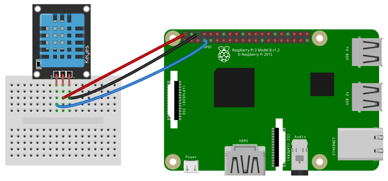
There are two variants of the DHT11 you’re likely to come across. One is a three pin PCB mounted module and the other is a four pin stand-alone module. The pinout is different for each one, so connect the DHT11 according to which one you have:

Also, some of the PCB mounted modules might have a different pinout than the one above, so be sure to check your sensor for any labels indicating which pin is Vcc, ground or signal.
Wiring for SSH Terminal Output
Three Pin DHT11 With SSH Output
If you have a three pin DHT11 and want to output the humidity and temperature to an SSH terminal, wire it like this:
Four Pin DHT11 With SSH Output
If you have a four pin DHT11 and want to output the humidity and temperature to the SSH terminal, wire it like this:
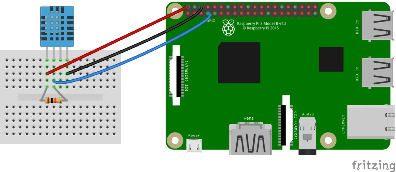
The resistor is a 10K Ohm pull up resistor connected between the Vcc and signal lines.
Wiring for LCD Output
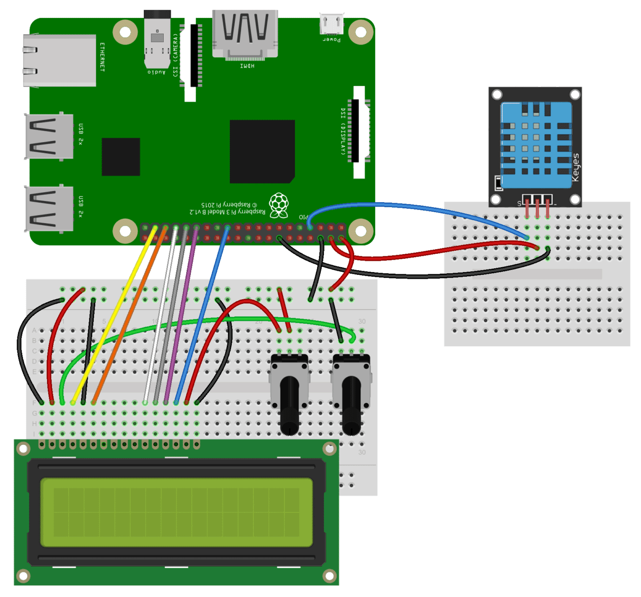
Three Pin DHT11 With LCD Output
If you want to output the temperature and humidity readings to an LCD display and have a three pin DHT11, connect it to the Pi like this:
Four Pin DHT11 With LCD Output
If you have a four pin DHT11 and want to output the temperature and humidity to an LCD display, connect it like this:
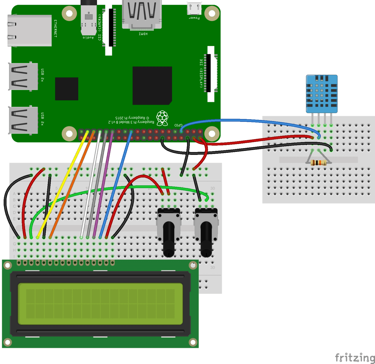
The resistor is a 10K Ohm pull up resistor connected between the Vcc and signal lines.
Programming the DHT11
I’ll explain how to use both C and Python to get temperature and humidity from the DHT11, so you’ll be able to incorporate the DHT11 into pretty much any existing RPi project.
If you’re not familiar with writing and running programs in Python or C on the Raspberry Pi, check out one of these tutorials:
- How to Write and Run a Python Program on the Raspberry Pi
- How to Write and Run a C Program on the Raspberry Pi
Programming the DHT11 With C
We’ll be using WiringPi to program the DHT11 in C. If you don’t have WiringPi installed already, follow this link for instructions on how to install WiringPi.
The examples below are stand-alone C programs, which will need to be saved to a file with a “.c” extension, then complied by entering this at the command prompt:
gcc -o example example.c -lwiringPi -lwiringPiDev
Change example and example.c to the file name you want to use.
Then run the program with:
sudo ./example
Output to an SSH Terminal
The following C program will output the humidity and temperature (in °C and °F) readings to an SSH terminal:
#include <wiringPi.h>
#include <stdio.h>
#include <stdlib.h>
#include <stdint.h>
#define MAXTIMINGS	85
#define DHTPIN		7
int dht11_dat[5] = { 0, 0, 0, 0, 0 };

void read_dht11_dat()
{
	uint8_t laststate	= HIGH;
	uint8_t counter		= 0;
	uint8_t j		= 0, i;
	float	f;

	dht11_dat[0] = dht11_dat[1] = dht11_dat[2] = dht11_dat[3] = dht11_dat[4] = 0;

	pinMode( DHTPIN, OUTPUT );
	digitalWrite( DHTPIN, LOW );
	delay( 18 );
	digitalWrite( DHTPIN, HIGH );
	delayMicroseconds( 40 );
	pinMode( DHTPIN, INPUT );

	for ( i = 0; i < MAXTIMINGS; i++ )
	{
		counter = 0;
		while ( digitalRead( DHTPIN ) == laststate )
		{
			counter++;
			delayMicroseconds( 1 );
			if ( counter == 255 )
			{
				break;
			}
		}
		laststate = digitalRead( DHTPIN );

		if ( counter == 255 )
			break;

		if ( (i >= 4) && (i % 2 == 0) )
		{
			dht11_dat[j / 8] <<= 1;
			if ( counter > 16 )
				dht11_dat[j / 8] |= 1;
			j++;
		}
	}

	if ( (j >= 40) &&
	     (dht11_dat[4] == ( (dht11_dat[0] + dht11_dat[1] + dht11_dat[2] + dht11_dat[3]) & 0xFF) ) )
	{
		f = dht11_dat[2] * 9. / 5. + 32;
		printf( "Humidity = %d.%d %% Temperature = %d.%d C (%.1f F)\n",
			dht11_dat[0], dht11_dat[1], dht11_dat[2], dht11_dat[3], f );
	}else  {
		printf( "Data not good, skip\n" );
	}
}

int main( void )
{
	printf( "Raspberry Pi wiringPi DHT11 Temperature test program\n" );

	if ( wiringPiSetup() == -1 )
		exit( 1 );

	while ( 1 )
	{
		read_dht11_dat();
		delay( 1000 );
	}

	return(0);
}
Output to an LCD
This C program will output the DHT11 readings to an LCD display:
#include <wiringPi.h>
#include <lcd.h>
#include <stdio.h>
#include <stdlib.h>
#include <stdint.h>

//USE WIRINGPI PIN NUMBERS
#define LCD_RS  25               //Register select pin
#define LCD_E   24               //Enable Pin
#define LCD_D4  23               //Data pin 4
#define LCD_D5  22               //Data pin 5
#define LCD_D6  21               //Data pin 6
#define LCD_D7  14               //Data pin 7
#define MAXTIMINGS 85
#define DHTPIN 7

int lcd;
int dht11_dat[5] = {0, 0, 0, 0, 0};

void read_dht11_dat()
{
        uint8_t laststate = HIGH;
        uint8_t counter = 0;
        uint8_t j = 0, i;
        float f;

        dht11_dat[0] = dht11_dat[1] = dht11_dat[2] = dht11_dat[3] = dht11_dat[4] = 0;

        pinMode(DHTPIN, OUTPUT);
        digitalWrite(DHTPIN, LOW);
        delay(18);

        digitalWrite(DHTPIN, HIGH);
        delayMicroseconds(40);

        pinMode(DHTPIN, INPUT);

        for (i = 0; i < MAXTIMINGS; i++)
        {
                counter = 0;
                while (digitalRead(DHTPIN) == laststate)
                {
                        counter++;
                        delayMicroseconds(1);
                        if (counter == 255)
                        {
                                break;
                        }
                }
                laststate = digitalRead(DHTPIN);

                if (counter == 255)
                        break;

                if ((i >= 4) && (i % 2 == 0))
                {
                        dht11_dat[j / 8] <<= 1;
                        if (counter > 16)
                                dht11_dat[j / 8] |= 1;
                        j++;
                }
         }

        if ((j >= 40) && (dht11_dat[4] == ((dht11_dat[0] + dht11_dat[1] + dht11_dat[2] + dht11_dat[3]) & 0xFF)))
        {
                f = dht11_dat[2] * 9. / 5. + 32;

                lcdPosition(lcd, 0, 0);
                lcdPrintf(lcd, "Humidity: %d.%d %%\n", dht11_dat[0], dht11_dat[1]);

                lcdPosition(lcd, 0, 1);
                //lcdPrintf(lcd, "Temp: %d.0 C", dht11_dat[2]); //Uncomment for Celsius
                lcdPrintf(lcd, "Temp: %.1f F", f); //Comment out for Celsius
        }
}

int main(void)
{
        int lcd;
        wiringPiSetup();
        lcd = lcdInit (2, 16, 4, LCD_RS, LCD_E, LCD_D4, LCD_D5, LCD_D6, LCD_D7, 0, 0, 0, 0);

        while (1)
        {
                read_dht11_dat();
                delay(1000);
        }

        return(0);
}
For temperature in Celsius, un-comment line 72 where it says lcdPrintf(lcd, "Temp: %d.0 C", dht11_dat[2]);, then comment out line 73. To find out more about how to control text on an LCD with C, check out How to Setup an LCD on the Raspberry Pi and Program it With C.
Programming the DHT11 With Python
We’ll be using the Adafruit DHT11 Python library. You can download the library using Git, so if you don’t have Git installed on your Pi already, enter this at the command prompt:
sudo apt-get install git-core
Note: If you get an error installing Git, run sudo apt-get update and try it again.
To install the Adafruit DHT11 library:
1. Enter this at the command prompt to download the library:
git clone https://github.com/adafruit/Adafruit_Python_DHT.git
2. Change directories with:
cd Adafruit_Python_DHT
3. Now enter this:
sudo apt-get install build-essential python-dev
4. Then install the library with:
sudo python setup.py install
Output to an SSH Terminal
This Python program will output the temperature and humidity readings to an SSH terminal:
#!/usr/bin/python
import sys
import Adafruit_DHT

while True:

    humidity, temperature = Adafruit_DHT.read_retry(11, 4)

    print 'Temp: {0:0.1f} C  Humidity: {1:0.1f} %'.format(temperature, humidity)
Output to an LCD
To output the DHT11 readings to an LCD, we’ll need to install another Python library called RPLCD to drive the LCD. To install the RPLCD library, we first need to install the Python Package Index, or PIP. PIP might already be installed on your Pi, but if not, enter this at the command prompt to install it:
sudo apt-get install python-pip
After you get PIP installed, install the RPLCD library by entering:
sudo pip install RPLCD
Once the library is installed, you can use the following code to output the DHT11 readings to an LCD:
#!/usr/bin/python
import sys
import Adafruit_DHT

from RPLCD import CharLCD

lcd = CharLCD(cols=16, rows=2, pin_rs=37, pin_e=35, pins_data=[33, 31, 29, 23])


while True:
    humidity, temperature = Adafruit_DHT.read_retry(11, 4)

    lcd.cursor_pos = (0, 0)
    lcd.write_string("Temp: %d C" % temperature)
    lcd.cursor_pos = (1, 0)
    lcd.write_string("Humidity: %d %%" % humidity)
Also, check out Raspberry Pi LCD Set Up and Programming in Python to see how to do things like scrolling and positioning text.
That should about cover most of what you’ll need to get the DHT11 up and running on your Raspberry Pi. Hope this made it easier for you. Be sure to subscribe if you liked this article and found it useful, and if you have any questions or need help with anything, just leave a comment below…


I received my DHT11 yesterday. Perfect timing ;-) Thank you for this awesome tutorial, keep it up !
Really helpful! Please try everyone:)
Isnt it better to use DHT22?
DHT11 has +/- 2°C accuracy while DHT22 has +/- 0.5°C
Can it be replaced?
Actually yes, the adafruit library supports all
of the DHT modules.
Any updates on the Adafruit code?
I seem to be getting a problem with the Raspberry_Pi_Driver
from . import Raspberry_Pi_Driver as driver
ImportError: cannot import name Raspberry_Pi_Driver
If not, I will try downloading the library etc again
Thanks
This error occurs when running the code from within the cloned the Adafruit_DHT directory.
No updates that I’m aware of… Just tested this on 3-24-17 and it still works. Maybe your internet was disconnected or there was a problem downloading the library?
somehow the C++ path gets error’s when compiling in the nano environment
I get:
DHTTEST.c: In function ‘read_dht11_dat’:
DHTTEST.c:52:2: error: expected ‘)’ before ‘{‘ token
{
^
DHTTEST.c:59:1: error: expected expression before ‘}’ token
}
^
Is there a easy fix for this or could anyone tell me what these error’s are about?
Thanks
I do get the same error..what’s wrong?
Is this working with Orangepi One ?
It only works on the terminal, when I try to do it with the LCD it wont work and I don´t know why. Im using a 1602A LCD, not sure if that`s the problem.
Is your LCD connected like it’s shown in the diagrams? If not you might have to change the pin numbers in the code. Also it could be that your LCD has a different pin out. Check out this diagram to see the pin out of the LCD I used to make the diagrams: https://i0.wp.com/www.circuitbasics.com/wp-content/uploads/2015/03/Arduino-LCD-Set-Up-and-Programming-Guide-LCD-Pinout.png
I am getting the error ¨Data not good, skip¨ while programming with C. Can anyone help me solve this problem?
Did you get your data not good, skip issue? That’s all I am getting for output. I have tried two different sensors now.
Hi,
i am getting continuously the “data not good” message with the c code, but everything is working fine with the python AdafruitDHT.py adafruit code sample. Does anyone know what the problem could be?
Thanks
I found the problem, I am still having a few “data not good” messages, but I get correct measurements too. The problem was here:
…
if ( (i >= 4) && (i % 2 == 0) )
{
dht11_dat[j / 8] < 16 )
dht11_dat[j / 8] |= 1;
j++;
}
…
Change 16 to 50 like this:
…
if ( (i >= 4) && (i % 2 == 0) )
{
dht11_dat[j / 8] < 50 )
dht11_dat[j / 8] |= 1;
j++;
}
…
The problem was that by receiving data from the sensor, the difference between the bit 0 and 1 is determined by the duration of HIGH voltage: 26-28us means 1 and 70us means 0. If you set the delimiter to 16 you always going to receive 0, and the checksum will fail, 50 should work.
The datasheet of Dht11, section 5.4:
https://www.mouser.com/ds/2/758/DHT11-Technical-Data-Sheet-Translated-Version-1143054.pdf
Sorry, I copied something wrong, the solution is:
Wrong:
if ( counter > 16)
dht11_dat[j / 8] |= 1;
j++;
Correct:
if ( counter > 50 )
dht11_dat[j / 8] |= 1;
j++;
Thanks for the correction to the code. Now it works.
The Python example was working so I knew the hardware and wiring was OK.
Now its working for me. Here and there I still getting data not good. but its understandable. Thanks Racz!!!
Hi, I made the correction you posted but still get the same problem… did you have to make any other changes to the code?
This is normal, I get the same message occasionally. It just means that one of the data transmissions was bad. The sensor should continue outputting data after a second or so.
That message appears when the sensor can’t read the tempeture & humidity, it´s not a programming error, something must be wrong with your sensor.
thanks, its just great.. i was wondering if you can help me with reading from SW420 sensor, i was able to get 0,1 values but i wanted to get if possible the actual value of the vibration
Hi. Thanks for the tutorial. got it working. i want to get more accurate than 1 degree +/- so will have a fiddle with the print line. cheers!
May I know which file should I run after executing “sudo python setup.py install” command???
After installing the library, copy the code and save it to a file with a “.py” extension, for example dht11.py. Then run the program with: python dht11.py
You can copy the text in Geany en then save as “TempHum.sh” and then execute.
The code works briliant but please can you help me how should python code looks if i want to have output in two lines. ? Temperature in one line and in next line humidity. Thank you
Mine shows temperature 11.0C and humidity 150%. I’m pretty sure both are quite wrong in this dry summer :-)
Divide 150 by 10= 15% humidity and the 11.0C Is probably referring to 110 Degrees Fahrenheit.
So, the C code works… the Python one does not.
At the end, it worked. Thing is, I have it on a Raspberry Pi 3, where it works without root, and in a Raspberry Pi 2, where it only works with root. I am not sure what I am doing wrong.
I remember reading that the GPIO on the Pi 3 no longer required root. Maybe this is why.
Hi,
Thanks for the tutorial. I got it working but with very strange readings like:
pi@raspberrypi:~/wiringPi $ sudo ./example
Raspberry Pi wiringPi DHT11 Temperature test program
Data not good, skip
Humidity = 1.74 % Temperature = 0.201 C (32.0 F)
Humidity = 1.74 % Temperature = 0.201 C (32.0 F)
Data not good, skip
Humidity = 1.74 % Temperature = 0.201 C (32.0 F)
Humidity = 1.74 % Temperature = 0.201 C (32.0 F)
The wiring seems correct.
I´m using DHT22, should I change anything in this C code? Do you have any suggestions?
Best regards,
Ricardo Gamba.
May be a fault with the sensor more than the programming. Or otherwise it could be Humidity x10 and temperature x100= your weather value?
did you solve this having same result even when i pull every 10 sec
hi, thanks for this tutorial i learned a lot about raspberry pi.
dear circuit basic , do you have a tutorial about RFM12B transciever module or do you have some suggestion about rfm12b how to set up ?
sorry for my bad english
Best regards,
Nanda muhammad
Works great, thanks.
nice post really helpful,i love it…please am doing project on automation, using java and avr microcontrollers but i dont realy know how to go about the part of interfacing the microcontroller with the computer using serial ports or usb i ahve already done the gui part of the project,,any help will be very helpful,,thanks in advance
Getting below error when trying to run LCD script, can anyone help?
/usr/local/lib/python2.7/dist-packages/RPLCD/lcd.py:213: RuntimeWarning: This channel is already in use, continuing anyway. Use GPIO.setwarnings(False) to disable warnings.
GPIO.setup(pin, GPIO.OUT)
Amazing tutorial I learned a lot with it.
I am not very familiar with developing codes but I am trying to integrate this with my zabbix Network Monitoring system. Instead of infinite loop the measures, how can I read and present just one measure.
Thanks for the great tutorial and any help is welcome.
I had this same error and my fix was just where I ran the Python script from. I placed my Python script inside the Adafruit_Python_DHT directory and I got the same error you are describing.
I copied the script to the directory above it (cp name.py ..), and ran it from that directory, and the script worked perfect.
Need help for Rpi 3
I get this error for the given python code:
Traceback (most recent call last):
File “1.py”, line 6, in
humidity, temperature = Adafruit_DHT.read_retry(11,4)
File “/home/pi/Adafruit_Python_DHT/Adafruit_DHT/common.py”, line 90, in read_retry
humidity, temperature = read(sensor, pin, platform)
File “/home/pi/Adafruit_Python_DHT/Adafruit_DHT/common.py”, line 76, in read
platform = get_platform()
File “/home/pi/Adafruit_Python_DHT/Adafruit_DHT/common.py”, line 51, in get_platform
from . import Raspberry_Pi_2
File “/home/pi/Adafruit_Python_DHT/Adafruit_DHT/Raspberry_Pi_2.py”, line 22, in
from . import Raspberry_Pi_2_Driver as driver
ImportError: cannot import name Raspberry_Pi_2_Driver
I moved my python code into the Adafruit source folder and managed to get it working from there
I had this same error and my fix was just where I ran the Python script from. I placed my Python script inside the Adafruit_Python_DHT directory and I got the same error you are describing.
I copied the script to the directory above it (cp name.py ..), and ran it from that directory, and the script worked perfect.
That’s strange… Which raspbian (Jessie full or Jessie lite) are you using? Which release was it? I just set it up again on my Pi 3 and didn’t have any problems. It looks like there was a problem with the library install. I would try to install it again…
i received same error. If i use the programs .py in examples folder, all it’s ok. If i use an other folder like home or desktop i receive that errors. i try also to copy the folder Adafruit_DHT that contain the module imprted, but never works. it works only in Adafruit_Python_DHT create like a clone from github
Did this ever work. I Am getting the similar error. Please let me know, how solved this?
very nice sir
I have this error then I try first script in python (without lcd)
Traceback (most recent call last):
File “./teplomer.py”, line 7, in
humidity, temperature = Adafruit_DHT.read_retry(11, 4)
File “/usr/local/lib/python2.7/dist-packages/Adafruit_DHT-1.3.1-py2.7-linux-armv7l.egg/Adafruit_DHT/common.py”, line 90, in read_retry
humidity, temperature = read(sensor, pin, platform)
File “/usr/local/lib/python2.7/dist-packages/Adafruit_DHT-1.3.1-py2.7-linux-armv7l.egg/Adafruit_DHT/common.py”, line 77, in read
return platform.read(sensor, pin)
File “/usr/local/lib/python2.7/dist-packages/Adafruit_DHT-1.3.1-py2.7-linux-armv7l.egg/Adafruit_DHT/Raspberry_Pi_2.py”, line 34, in read
raise RuntimeError(‘Error accessing GPIO.’)
RuntimeError: Error accessing GPIO.
Can you help me? Thanks
Have the same problem, did you find any solution?
thank you sir its greats
Thanks for the article. It was very helpful. I mostly used the C code, and when I upgraded to the DHT22,I modified your code to support both devices. In case anyone else wants to use it, it’s below. On the command line, add two parameters for device and io_pin. Example:
./read_data 11 4
to read from a DHT11 on pin 7
or ./read_data 22 7
to read from DHT22 from pin 4
—
#include
#include
#include
#include
#define MAXTIMINGS 85
#define DHTPIN 7
int dht_dat[5] = { 0, 0, 0, 0, 0 };
int read_dht_dat(int device, int pin)
{
uint8_t laststate = HIGH;
uint8_t counter = 0;
uint8_t j = 0, i;
dht_dat[0] = dht_dat[1] = dht_dat[2] = dht_dat[3] = dht_dat[4] = 0;
pinMode( pin, OUTPUT );
digitalWrite( pin, LOW );
delay( 18 );
digitalWrite( pin, HIGH );
delayMicroseconds( 40 );
pinMode( pin, INPUT );
for ( i = 0; i = 4) && (i % 2 == 0) )
{
dht_dat[j / 8] < 16 )
dht_dat[j / 8] |= 1;
j++;
}
}
if ( (j >= 40) &&
(dht_dat[4] == ( (dht_dat[0] + dht_dat[1] + dht_dat[2] + dht_dat[3]) & 0xFF) ) )
{
if (device == 11) {
float f;
f = dht_dat[2] * 9. / 5. + 32;
printf( “Humidity = %d.%d %% Temperature = %d.%d C (%.1f F)\n”,
dht_dat[0], dht_dat[1], dht_dat[2], dht_dat[3], f );
} else {
// DHT22
float hum;
float temp_c;
float f;
hum = (dht_dat[0] * 256 + dht_dat[1]) / 10.0;
temp_c = (dht_dat[2] * 256 + dht_dat[3]) / 10.0;
f = temp_c * 9. / 5. + 32;
printf( “Humidity = %.02f %% Temperature = %.02f C (%.1f F)\n”, hum, temp_c, f);
}
return 0;
}else {
printf( “Data not good, skip\n” );
return 1;
}
}
int main( int argc, char **argv )
{
int done = 0;
int device = 0;
int pin = 0;
//printf(“argc: %d\n”, argc);
if (argc != 3) {
printf(“usage: read_dht11 [11|22] \n”);
exit(1);
} else {
device = strtol(argv[1], NULL, 10);
pin = strtol(argv[2], NULL, 10);
//printf (“device: %d, pin: %d\n”, device, pin);
if (device != 11 && device != 22) {
printf(“usage: read_dht11 [11|22] \n”);
exit(1);
}
}
printf( “Raspberry Pi wiringPi DHT11 Temperature test program\n” );
if ( wiringPiSetup() == -1 )
exit( 1 );
while ( !done )
{
int ret;
done = read_dht_dat(device, pin) ? 0 : 1;
delay( 1000 );
}
return(0);
}
thank you so much
its really working
if you have soil moisture sensor interfacing code and logic than please replay me
thank you so much
My code is same as pythone code
And i got erroe like
Value error : unknown format code ‘f’ for object of type ‘str’
Please give me solution
Same error here. Did you get past this?
yes still not working
Ok finally got past this. The jumper wire shipped with sensor was faulty so the GPIO read was failing. Started with checking colleague’s LED sensors to work with my PI which when worked tried DHT11 with colleague’s PI which when worked then switched wires and tried with my PI! You may want to check wiring and sensor. The code is just fine.
Works for me! Rocking the python code! Tnxz!
convert Celsius to Farenheit with this Python Code for SSH display…
#!/usr/bin/python
import sys
import Adafruit_DHT
while True:
humidity, temperature = Adafruit_DHT.read_retry(11, 4)
convert = temperature * 1.8 + 32
print ‘Temp: {0:0.1f} C Humidity: {1:0.1f} %’.format(convert, humidity)
OOPs C after {0:0.1f} should be F
thank you
i got error in #!/usr/bin/python ….what should i do?
try:
which python
This will tell you the path to python on your particular computer. [It may not be installed.]
i’m trying to make this work but only works python to console when i try to make it works with lcd
i get such error:
./lcd.py
/usr/local/lib/python2.7/dist-packages/RPLCD/lcd.py:213: RuntimeWarning: This channel is already in use, continuing anyway. Use GPIO.setwarnings(False) to disable warnings.
GPIO.setup(pin, GPIO.OUT)
Traceback (most recent call last):
File “./lcd.py”, line 6, in
lcd = CharLCD(cols=16, rows=2, pin_rs=7, pin_e=8, pins_data=[25, 24, 23, 18])
File “/usr/local/lib/python2.7/dist-packages/RPLCD/lcd.py”, line 213, in __init__
GPIO.setup(pin, GPIO.OUT)
ValueError: The channel sent is invalid on a Raspberry Pi
i cant also make it works with c program :( even to console my lcd is connected with 4 bit mode
http://www.raspberrypi-spy.co.uk/2012/07/16×2-lcd-module-control-using-python/
and this script is working and can see information on screen but for me is important to make temperature and humidity so i can have thermometer in my 3d printer enclosure..
Please help
Are your pin numbers BOARD pin numbers or BCM pin numbers? The RPLCD library needs BOARD pin numbers. Also, do you know which version of RPi.GPIO you have? Try running this to find out: find /usr | grep -i gpio
If your RPi.GPIO version is 0.5.6 or earlier, there was bug that caused some pins on the expanded header to not work. You can update RPi.GPIO by running this command:
sudo apt-get update && sudo apt-get install python-rpi.gpio python3-rpi.gpio
Let me know if that fixes it…
#raspberrypi #diy ordered me a few more bits so I can do this ?
I keep getting this error
Traceback (most recent call last):
File “Tempreture.py”, line 7, in
humidity, temperature = Adafruit_DHT.read_retry(35, 2)
File “build/bdist.linux-armv7l/egg/Adafruit_DHT/common.py”, line 94, in read_retry
File “build/bdist.linux-armv7l/egg/Adafruit_DHT/common.py”, line 78, in read
ValueError: Expected DHT11, DHT22, or AM2302 sensor value.
Hi Ikya :)
I have the same error as you. Did you ever solve yours ? Can’t seem to find an answer anywhere :)
Hi,
It can’t be 35 in this line
humidity, temperature = Adafruit_DHT.read_retry(35, 2)
That is refering to type of sensor and since this tutorial is about DHT 11 it should be 11
humidity, temperature = Adafruit_DHT.read_retry(11, 2)
That’s perfect!
You make my day, thanks a lot guys!
Traceback (most recent call last):
File “q.py”, line 7, in
humidity, temperature = Adafruit_DHT.read_retry(7,4)
File “/home/pi/Adafruit_Python_DHT/Adafruit_DHT/common.py”, line 94, in read_retry
humidity, temperature = read(sensor, pin, platform)
File “/home/pi/Adafruit_Python_DHT/Adafruit_DHT/common.py”, line 78, in read
raise ValueError(‘Expected DHT11, DHT22, or AM2302 sensor value.’)
ValueError: Expected DHT11, DHT22, or AM2302 sensor value.
this error is shown ..can anyone help?/
The first argument to read_retry (the first number in parentheses) HAS to be 11 in this case (it refers to the type of sensor – DHT11).
PROGRAMMING THE DHT11 three pin PCB+LCD (16*2)+raspberry pi B WITH PYTHON
I successfully setup my pi with the sensor. Great tutorial! However, I would like to know about the code about this line
humidity, temperature = Adafruit_DHT.read_retry(11, 4)
May I ask about what does (11,4) is referring to? I am thinking that it is the GPIO Addreess but it’s not. I guess. Could somebody lend their ideas? Thank you and more power.
Here 11 is the temperature sensor name you are using like here it’s DHT11 and the 4 is the GPIO address pin that you connect to the sensor.
I tried the following code into my Respberry pi 3 and it says
Traceback (most recent call last):
File “testtemp.py”, line 9, in
print ‘Temp: {0:0.1f} C Humidity: {1:0.1f} %’.format(temperature, humidity)
ValueError: Unknown format code ‘f’ for object of type ‘str’
how can I fix it?
try to replace line print …. with print (temperature) so you can understand if you receive data.
Hi guys. I have a dth11 sensor with 3 pins as shown in the post. I made the correct connections. But the Vcc and GND wires start to burn and the plastic insulation begins to melt. I double checked the gpio Vcc supply pin and GND pin with a multimeter and it’s showing 5V. Any idea what went wrong?
it happned also to me, maybe you invert that two pin. Vcc has to go to + or 5v and gnd has to go to ground.
Sorry if this is a newbie question, but I’m just curious – why did you power the DHT11 at 5V? Doesn’t this mean that we get a maximum voltage of 5V on the input GPIO? (which I understand is not a great idea for a device that normally runs at 3.3V)
According to the DHT11 datasheet, power supply can be 3 to 5.5V, so it should work at 3.3V as well.
Is there another reason for this design choice?
Thank you!
I think this is a great point! I am going to use the 3.3V pin on the Pi to power mine. Otherwise the serial signal line from the sensor will swing up to 5V, and the Pi GPIO pins are not 5V tolerant.
Maybe a really stupid question but better asked.
When looking at the c program I see use wiringpi PIN numbers.
For example LCD_RS 25
When I look at wiringpi documentation pin 25 doesn’t exist.
In the video it says GPIO 26 pin 37???
Thanks
It looks like wiringpi uses its own set of numbers – it’s not the BCM GPIO numbering, and it’s not physical pin numbering (although it can support these two as well).
https://projects.drogon.net/wiringpi-pin-numbering/
A strange design decision indeed… And even more strange is that the author still stands by his original choice, and recommends using that numbering :)
Hmm,,,, still don’t get it fully.
I found this link at that site.
http://wiringpi.com/wp-content/uploads/2013/03/pins.pdf
But there is no wiringpi number above 20?
Thanks
hi, Thanks for the tutorial. Excellent.
My setup is RPi2, DHT11 (with board, 3 pin ), reading temperature and humidity and displaying on the 16×2 LCD
Running the script
——–
#!/usr/bin/python
import sys
import Adafruit_DHT
from RPLCD import CharLCD
lcd = CharLCD(cols=16, rows=2, pin_rs=37, pin_e=35, pins_data=[33, 31, 29, 23])
while True:
humidity, temperature = Adafruit_DHT.read_retry(11, 17)
lcd.cursor_pos = (0, 0)
lcd.write_string(“Temp: %d C” % temperature)
lcd.cursor_pos = (1, 0)
lcd.write_string(“Humidity: %d %%” % humidity)
——————————-
Getting the following error
————————
>>>
Traceback (most recent call last):
File “/home/pi/dht11_lcd.py”, line 7, in
lcd = CharLCD(cols=16, rows=2, pin_rs=37, pin_e=35, pins_data=[33, 31, 29, 23])
File “/home/pi/RPLCD/__init__.py”, line 14, in __init__
super(CharLCD, self).__init__(*args, **kwargs)
File “/home/pi/RPLCD/gpio.py”, line 95, in __init__
‘must be either GPIO.BOARD or GPIO.BCM’ % numbering_mode)
ValueError: Invalid GPIO numbering mode: numbering_mode=None, must be either GPIO.BOARD or GPIO.BCM
>>>
I figured it out. Added numbering_mode parameter to the call as follows
—
#!/usr/bin/python
import sys
import Adafruit_DHT
import RPi.GPIO as GPIO
from RPLCD import CharLCD
GPIO.setwarnings(False)
## If using BOARD numbers such as PIN35, PIN31 etc, uncomment the line below
##lcd = CharLCD(numbering_mode=GPIO.BOARD,cols=16, rows=2, pin_rs=37, pin_e=35, pins_data=[33, 31, 29, 23])
## If using BCM numbers such as GPIO13, GPIO11 etc), uncomment the line below
lcd = CharLCD(numbering_mode=GPIO.BCM,cols=16, rows=2, pin_rs=26, pin_e=19, pins_data=[13,6, 5, 11])
while True:
humidity, temperature = Adafruit_DHT.read_retry(11, 17)
lcd.cursor_pos = (0, 0)
lcd.write_string(“Temp: %d C” % temperature)
lcd.cursor_pos = (1, 0)
lcd.write_string(“Humidity: %d %%” % humidity)
i am getting the o/p as shown below,can someone help me whats wrong in the code?
import sys
import Adafruit_DHT
import RPi.GPIO as GPIO
from RPLCD import CharLCD
GPIO.setwarnings(False)
lcd = CharLCD(numbering_mode=GPIO.BCM,cols=16, rows=2, pin_rs=26, pin_e=19, pins_data=[13,6,5,11])
while True:
humidity , temperature = Adafruit_DHT.read_retry(11, 4)
lcd.cursor_pos = (0, 0)
lcd.write_string(“Temp: %d C” %temperature)
lcd.cursor_pos = (1, 0)
lcd.write_string(“Humidity: %d %%” %humidity)
pi@piadi:~$ python dhtlcd2.py
File “dhtlcd2.py”, line 14
SyntaxError: Non-ASCII character ‘\xe2’ in file dhtlcd2.py on line 14, but no encoding declared; see http://python.org/dev/peps/pep-0263/ for details
It’s a stray character from the editor you used for the code. Did you by any chance copy/paste the code (including some smart quotes)?
Double-check your quotes, and make sure the editor you use is a text-only (even better, ASCII-only) one :)
See here for more details:
https://stackoverflow.com/questions/21639275/python-syntaxerror-non-ascii-character-xe2-in-file
I had the same GPIO error as you Raghu, but your additions just give me a different set of errors…
Traceback (most recent call last):
File “th2.py”, line 17, in
humidity, temperature = Adafruit_DHT.read_retry(11,17)
File “/home/pi/Adafruit_Python_DHT/Adafruit_DHT/common.py”, line 94, in read_retry
humidity, temperature = read(sensor, pin, platform)
File “/home/pi/Adafruit_Python_DHT/Adafruit_DHT/common.py”, line 80, in read
platform = get_platform()
File “/home/pi/Adafruit_Python_DHT/Adafruit_DHT/common.py”, line 48, in get_platform
from . import Raspberry_Pi
File “/home/pi/Adafruit_Python_DHT/Adafruit_DHT/Raspberry_Pi.py”, line 22, in
from . import Raspberry_Pi_Driver as driver
ImportError: cannot import name Raspberry_Pi_Driver
Can anyone make a suggestion?? for a senior, junior pi enthusiast…
Pete
I have just run into the exact same issue right now, on a brand new Raspberry Pi :)
In my case, the issue was related to the fact that the default Python interpreter is Python2, but my Python code was set to use Python3.
I just had to to “python3 setup.py install” when setting up the Adafruit DHT library, to make sure that it gets installed under the correct interpreter.
Maybe this will help you as well :)
@Pete – To add to my previous comment – make sure that you followed all the above steps for installing the Adafruit DHT library. If you’re not sure, just reinstall it :)
You have a line that says “from . import Raspberry_Pi_Driver as driver”.
Do you actually have that “Raspberry_Pi_Driver.py” file?
HI,
i did follow all of the method, twice but had the same result… That Pi Driver file threw me a curve ball as I cant find one on the pi and cant find what it is to locate one.
Im going to throw some more time at this through this week so if you have any suggestions I would be most grateful.
CHeers
Pete
Awesome,
Sorry Im reading backwards up the list… Yes I am on the latest version of Pi so will try the Python3 setup, thank you,
Pete
Hello and greetings from Boston, MA. THANK YOU, THANK YOU, THANK YOU!!!
I’ve got an Arduino Mega 2560 R3 running on my Macbook Pro High Sierra with a DHT11 3pin sensor. If I connect the sensor to the Raspberry PI using a breadboard, and via either SSH or a Serial Console cable, this tutorial runs flawlessly. HOWEVER, if I connect the Arduino to the Macbook directly or via the Mac, I receive the following error:
Arduino: 1.8.5 (Mac OS X), Board: “Arduino/Genuino Mega or Mega 2560, ATmega2560 (Mega 2560)”
Sketch uses 6900 bytes (2%) of program storage space. Maximum is 253952 bytes.
Global variables use 318 bytes (3%) of dynamic memory, leaving 7874 bytes for local variables. Maximum is 8192 bytes.
avrdude: ser_open(): can’t open device “/dev/cu.usbserial”: No such file or directory
ioctl(“TIOCMGET”): Inappropriate ioctl for device
ioctl(“TIOCMGET”): Inappropriate ioctl for device
avrdude: ser_send(): write error: Bad file descriptor
avrdude: stk500_send(): failed to send command to serial port
avrdude: stk500v2_ReceiveMessage(): timeout
avrdude: ser_send(): write error: Bad file descriptor
avrdude: stk500_send(): failed to send command to serial port
avrdude: stk500v2_ReceiveMessage(): timeout
avrdude: ser_send(): write error: Bad file descriptor
avrdude: stk500_send(): failed to send command to serial port
avrdude: stk500v2_ReceiveMessage(): timeout
avrdude: ser_send(): write error: Bad file descriptor
avrdude: stk500_send(): failed to send command to serial port
avrdude: stk500v2_ReceiveMessage(): timeout
avrdude: ser_send(): write error: Bad file descriptor
avrdude: stk500_send(): failed to send command to serial port
avrdude: stk500v2_ReceiveMessage(): timeout
avrdude: ser_send(): write error: Bad file descriptor
avrdude: stk500_send(): failed to send command to serial port
avrdude: stk500v2_ReceiveMessage(): timeout
avrdude: stk500v2_getsync(): timeout communicating with programmer
the selected serial port avrdude: stk500v2_getsync(): timeout communicating with programmer
does not exist or your board is not connected
This report would have more information with
“Show verbose output during compilation”
option enabled in File -> Preferences.
This little thing makes me soon mad …
I get this little import error on the module RPLCD but it claims to be installed …
pi@raspberrypi ~/Adafruit_Python_DHT $ sudo pip install RPLCD
Requirement already satisfied (use –upgrade to upgrade): RPLCD in /usr/local/lib/python2.7/dist-packages/RPLCD-0.4.0-py2.7.egg
Cleaning up…
pi@raspberrypi ~/Adafruit_Python_DHT $ sudo python3 20171114.py
Traceback (most recent call last):
File “20171114.py”, line 6, in
from RPLCD import CharLCD
ImportError: No module named RPLCD
pi@raspberrypi ~/Adafruit_Python_DHT $
a
Any advice?
Thanks
See above my previous comment (the one posted on October 30).
You do have TPLCD installed under python2, but you are using python3 to run your code :)
Try doing a “sudo pip3 install RPLCD”, then try running your program again.
Typo – I wrote TPLCD, but I meant RPLCD. Sorry about that :)
Hi,
Didn’t work
Got an error
Sudo: pip3 unknown command
Or something similar. Thought I posted immediately but apparently not
Thanks
You need to install pip for python3:
sudo apt-get install python3-pip
Thanks!
Will try that later today.
Hi
I would like to try this little project as my first one in this new hobby.
But I didn’t see what you use to complet your projet. I know you have a raspberry pi (obviously) and a DHT11 (or 22) sensor, projects boards, but what else?
I would like to know what kind of raspberry pi can we use to build this thing up? (previous versions of pi are usually sold bit cheap than the new version).
what kind of LCD you have used?
What kind of wires will I need to soldering to complet the project? (I’m suppose I will be able to soldering those wire together at the end after all the project work well on the projects boards right?)
What is the capacity of the SDMicro card I need to have? And what OS should I use / boot on this card?
What are those “big golden rounds things” (top right of you largest project board) …. look like a kind of buzzer
Thank
@boubou – I will try to answer all of your questions.
1) All you need is a raspberry pi, a sensor, a breadboard, and (optionally) an LCD screen. You can make your own connection wires, but it will make things a lot easier for you if you buy them already made (with male or female connectors in the ends, like the ones you see in the pictures)
2) Any Raspberry Pi will do.
3) The LCD used is a generic “1602” (16×2, or 16 characters/2 lines).
4) If you want to solder the completed project, you will also need some kind of PCB to solder everything onto. The types of wires used doesn’t really matter at this point :)
5) I would recommend using NOOBS or Raspbian (the two “official” OSs for Raspberry Pi). IIRC, any microSD card of more than 2 GB will work.
6) The “big golden round things” are variable resistors (potentiometers). He’s using them to control the brightness and contrast of the LCD screen.
One more thing – based on your questions, I assume that the Raspberry Pi is a new platform for you. I would strongly recommend that you read some “getting started” guides, and work on some simpler projects (like blinking a LED connected to a GPIO) before tackling this one. While this is not an overly complicated project, it does have multiple parts, and could be a bit overwhelming as a first Pi project :)
Hi
thank alot for ansering.
Well I will buy an old version of the pi (Raspberry Pi Model A+ 512MB RAM). As I said, less expansive than the newer one.
well, I will love to see what going one with the temperature and humidity … so the LCD screen should be good for me.
My question is: with this set up, can we record the datas? I don’t need to see far away back … but if I can see what was the temperature / humidity couple days ago I will be glad (it a projet for my “cheese cave”). That is why I asked for the capacity of the card.
Do you know what kind of PCB I will need? I found a 5 X 7 cm. will it be enough?
I didn’t know we needed potentiometers to control the brightness and contrast of the LCD screen. Tought we can do it with “on screen control”. I will see if I need one or not. (it may not be necessary for my project).
Yes it new for me … but I already read a little bit on this sujet. Like you suggest, I readed some kind of magazines (like the magpi, Raspberry Pi For Beginners or for kids). I may not read it all, but I think I got the picture. The hardest part for me will certainly be the programming section wish I’m completly new to this and never code anything.
But with this kind of project I think I will be able to learn.
You can record them, but you will need to write your own code for that. And decide on how to do that (log to a text file? to a database?). Also, you will need to write your own code to clean up old data. And your own code to recall and display previous values.
The capacity of the card doesn’t really matter – since you’re only storing a few bytes of text for each entry, you can store many years’ worth of data in a single GB :) .
For the PCB I recommend the pre-drilled kind – the size depends only on how close you want (and can :) ) solder everything together.
As for the LCD, the potentiometers are required. I would recommend you to also have a look at the I2C version of the LCDs – basically the same type of screen, but with an I2C “backpack”/”shield” already connected. That shield includes the potentiometers, and allows you to talk to the LCD by using only 4 wires. However, the code will look a bit different – google for “raspberry pi i2c lcd”, and you will find plenty of examples.
If you google a bit there is code and setup to write the values to a google spreadsheet. Easy from there to export to Excel or anything else.
Hi, Thanks for the tutorial. It’s really excellent.
The python code works on the terminal.
When I try to do it with the LCD it won’t work.
I’m using a 1602 LCD, but I think it’s not the problem.
This is the error I got:
Traceback (most recent call last):
File “DHT11_LCD.py”, line 7, in
lcd = CharLCD(cols=16, rows=2, pin_rs=37, pin_e=35, pins_data=[33, 31, 29, 23])
File “/usr/local/lib/python2.7/dist-packages/RPLCD/__init__.py”, line 14, in __init__
super(CharLCD, self).__init__(*args, **kwargs)
File “/usr/local/lib/python2.7/dist-packages/RPLCD/gpio.py”, line 95, in __init__
‘must be either GPIO.BOARD or GPIO.BCM’ % numbering_mode)
ValueError: Invalid GPIO numbering mode: numbering_mode=None, must be either GPIO.BOARD or GPIO.BCM
My RPi.GPIO version is 0.6.3. I hope that this can help you to solve my problem.
I’m sorry that I’m not really good at English.
Thanks for the tutorial again. This is the best tutorial I have seen.
I am looking forward to receive your reply.
So I succesfully ran this program, but I always get the message “Data not good, skip”. Is something wrong with my sensor? It works in python…
I might add that this is a cheap module that I bought on ebay, maybe something is wrong?
Managed to solve it, had to increase the delay from 1 micro second to 2 micro seconds.
I was facing the same issue of “Data not good, skip” messages and not even one proper reading appearing.
Increasing delay to 2 microseconds (even 3 microseconds) has fixed this issue. Thanks a ton Baxtex, for your suggestion.
How the heck do you read digital input for that sensor? Raspberry doesn’t have any digital or analog output.
@Marius – what are you talking about? Raspberry has TONS of digital I/O pins :)
Yes, it doesn’t have any analog pins (no ADC/DAC onboard), but since this is a digital sensor, you don’t need those anyway :)
Well, I have strange problem… I can’t get input for any sensors. I have a RaspberryPi 3 B, https://www.ebay.com/itm/DHT11-Digital-Temperature-and-Humidity-Sensor-Module-for-Raspberry-Pi-Arduino-/290960723731, https://www.ebay.com/itm/LCD-1602A-16×2-Zeichen-Display-Blau-Schwarz-HD44780-LCD1602-Arduino-Raspberry/142613981942?hash=item213474aaf6:g:rY4AAOSwAHBaJQfg, https://www.ebay.com/itm/Freenove-Gas-Sensor-Board-for-Arduino-Raspberry-Pi-3-3V-5V/302027776550?hash=item4652422226:g:BIEAAOSw0fhXli9a and https://www.sparkfun.com/products/11769 . I’m using Raspbian as OS and all I can do is to turn on and off leds… nothing more. I tried to get input for all sensors mentioned above, but I can’t get from any of them. I did every step mentioned above in the tutorial (with the C part) but still no result. I never worked with Raspberry, this is my first time… but it’s not like I don’t know what I do. I have basic knowledge about Ardunio and it’s pretty same thing. The interesting part is that all of my sensors work on Arduino but not on Raspberry… after one day of research, my only theory is that I need a sensor shield to be able to get input from my sensors. But again, in your tutorial there is nothing mentioned about this.
digitalRead gives me always 1 as value…
You _really_ need to provide more details… What is connected to the pin that you are reading? If it is the DHT11 sensor, you don’t simply read the pin – read the datasheet (or the code in the article above) to see what you need to send, and what the sensor sends back to you on that pin.
Well I have the + to PIN 2, – to PIN 9 and OUT to pin 7. That’s all… The code should do the magic, but seems like it does not.
I read the datasheet and I understod that input from sensor is actually a message formed by 5 bytes and all the other details, nothing too fancy… the main problem is that every single bit from my message is equal to 1.
Many things that could go wrong here…
1) Are you using the code in the article? (exactly that code, or a modified version?)
2) What type of DHT11 do you have (3-pin, or 4-pin)? Do you have a pullup resistor in place?
3) Just in case, do you have another DHT11 you could test with?
Sorry for asking… are this photos and videos made by you? The problem doesn’t seem to be only at me, I made some research and there are plenty of people complaining about exactly the same problem. It’s still doesn’t make any sense since in the datasheet it’s written that the input is digital signal…
No, the page is not mine. I’m just another user trying to help people out :)
The pull-up resistor should be a 10K resistor connected between Vcc (+5V) and the signal pin of the DHT. The 3-pin version should already have a pull-up resistor on the board (see the first picture of the 3-pin DHT sensor in the article above) – but I did have some 3-pin DHT sensors from China that were missing that resistor.
However, if the sensor works on Arduino, this is probably NOT the issue.
Right now, the only other advice I can give you is “double- and triple-check all your wiring”. Maybe also try with another GPIO pin, to make sure that is not the issue.
Well, I think there are two resistors, but on the other side of the sensor, comparing to the image.
My wiring is good, I tried to get input with the sensor disconnected… values were all 0. Right after I connected the sensor back, the values became all 1.
Thanks for trying and sorry for wasting your time! :)
Yes, exactly the code from article.
I have the 3 pin version. Sorry but I don’t know what is exactly a pullup resistor. There is only the sensor and the Raspberry.
Nope, I don’t have another DHT11, but I know 100% that it’s working because I just tested it today on Arduino. I think it’s a configuration problem… I can’t get the LCD display working, neither the gas sensor. The raspberry it’s not broken neither, I have two of them and the problem is the same… also, I can turn on and off leds, and I also can get input from a button, but not from the sensors.
Thanks for your time
((((could u make it to send results in our desired regular intervals of time to our mentioned mail from this below program))))
#!/usr/bin/python
import sys
import Adafruit_DHT
while True:
humidity, temperature = Adafruit_DHT.read_retry(11, 4)
print ‘Temp: {0:0.1f} C Humidity: {1:0.1f} %’.format(temperature, humidity)
Short answer: yes.
Long answer: you will need to read on how to send an email from python, and how to run a program at regular intervals.
For the first part, see here for some examples: https://docs.python.org/2/library/email-examples.html
For the second part, you can run your program at startup and keep it running continuously (a “while True:” loop that simply sends the email, then sleeps for the desired time). Or, even better, you can run your program periodically using cron.
Hi.
I’m new at Pi3.I have a question. I see this below message. I have no idea what to do.
Traceback (most recent call last):
File “t.py”, line 7, in
humidity, temperature = Adafruit_DHT.read_retry(11, 4)
File “/home/pi/Adafruit_Python_DHT/Adafruit_DHT/common.py”, line 94, in read_retry
humidity, temperature = read(sensor, pin, platform)
File “/home/pi/Adafruit_Python_DHT/Adafruit_DHT/common.py”, line 80, in read
platform = get_platform()
File “/home/pi/Adafruit_Python_DHT/Adafruit_DHT/common.py”, line 55, in get_platform
from . import Raspberry_Pi_2
File “/home/pi/Adafruit_Python_DHT/Adafruit_DHT/Raspberry_Pi_2.py”, line 22, in
from . import Raspberry_Pi_2_Driver as driver
ImportError: cannot import name Raspberry_Pi_2_Driver
Could someone tell me what is problem?
Thank you.
This has been asked at least 4 times before (and answered). Please search the comments (Ctrl-F, and type “driver”, for example) – you will find possible solutions.
Hi there,
How do I transfer this information to the mobile app? Is there a way to code this simply so it shows live on the android app?
For me, my case is where 90% are failed check-sum [Data not good, skip] and only 10% data retrieved successfully. I’ve modified the code to “100% eliminated” the [Data not good, skip] statement display during the data retrieving. The code I modified didn’t actually eliminate the fail check-sum, but to decrease the looping m/s for faster refresh rate and removed printf( “Data not good, skip\n” ); to stop displaying the [Data not good, skip]
//Modified code block
if ( (j >= 40) &&
(dht11_dat[4] == ( (dht11_dat[0] + dht11_dat[1] + dht11_dat[2] + dht11_dat[3]) & 0xFF) ) )
{
f = dht11_dat[2] * 9. / 5. + 32;
printf( “Humidity = %d.%d %% Temperature = %d.%d C (%.1f F)\n”,
dht11_dat[0], dht11_dat[1], dht11_dat[2], dht11_dat[3], f );
}else {
//printf( “Data not good, skip\n” );// //<set this line as comment//
}
}
//and//
while ( 1 )
{
read_dht11_dat();
delay( 100 );
}
Correct me if I did a stupid mistake, thank you!
Sorry If this was already answered, but when I run my code, I get the message
File “Tah.py”, line 8
lcd = CharLCD(cols=16, rows=2, pin_rs=37, pin_e=35, pins_data[33, 31, 29, 23])
SyntaxError: non-keyword arg after keyword arg
Here’s the code
#!/usr/bin/python
import sys
import Adafruit_DHT
from RPLCD import CharLCD
lcd = CharLCD(cols=16, rows=2, pin_rs=37, pin_e=35, pins_data[33, 31, 29, 23])
while True:
humidity, temperature = Adafruit_DHT.ready_retry(11, 4)
convert = temperature*1.8+32
lcd.cursor_pos = (0, 0)
lcd.write_string(“Temp: %d F” % temperature)
lcd.cursor_pos = (1, 0)
lcd.write_string(“Humidity: %d %%” % humidity)
Any help would be appreciated!
As the output tells you, the error has nothing to do with the DHT11. The error is on the “lcd” line.
It should be like this (copied from the article above):
lcd = CharLCD(cols=16, rows=2, pin_rs=37, pin_e=35, pins_data=[33, 31, 29, 23])
You are missing the equal sign (=) after pins_data, and this creates a function call that is invalid in Python (if you are curious why, look up “keyword arguments”, and you will see that all non-keyword arguments must occur _before_ any keyword argument).
Hello, Need help in RaspberryPi-3. I actually worked with dht22 sensor and raspberry-pi but when i ran the code i got this kind of error –
File “/var/www/lab_app/ft1.py”, line 11, in lab_app
humidity,temperature = Adafruit_DHT.read_retry(Adafruit_DHT.AM2302, 18)
File “build/bdist.linux-armv7l/egg/Adafruit_DHT/common.py”, line 94, in read_retry
humidity, temperature = read(sensor, pin, platform)
File “build/bdist.linux-armv7l/egg/Adafruit_DHT/common.py”, line 81, in read
return platform.read(sensor, pin)
File “build/bdist.linux-armv7l/egg/Adafruit_DHT/Raspberry_Pi_2.py”, line 34, in read
raise RuntimeError(‘Error accessing GPIO.’)
RuntimeError: Error accessing GPIO.
*****Please help me out****
You’re saying that you’re using a DHT22, but you’re doing read_retry(AM2302)? The first argument to read_retry should be “22” for DHT22
How do i connect 3 DHT11?
i am making a project with RPi and i need 3 DHT’s
Please Help
Use three different GPIO pins on the raspberry pi, and read them individually. It really is as simple as that :)
For example, if you’re using Python, you can read three DHT11 sensors on GPIO 4, 5, and 6 like this:
humidity1, temperature1 = Adafruit_DHT.read_retry(11, 4)
humidity2, temperature2 = Adafruit_DHT.read_retry(11, 5)
humidity3, temperature3 = Adafruit_DHT.read_retry(11, 6)
It worked for me
Thank you very much ;)
Hi,
I’m having a problem in getting the C program to run (on terminal). It only shows “Data not good, skip” and I never get a valid reading.
The only change I did was to use GPIO pin 25 instead of 7 (I tried several GPIO pins including 7)
#define DHTPIN 25
I tested the Python version and it runs without any issues with the same wiring. In this case I entered BCM pin number 26 which corresponds to wiringPi pin 25.
So I guess my jumper cable wiring is correct and my GPIOs are still functional.
Any ideas on how to debug this?
I found a solution here:
https://www.raspberrypi.org/forums/viewtopic.php?t=197331
changing “counter > 16” to “counter > 50” solved the issue.
Hello,
I am unable to start the script because of this error:
Traceback (most recent call last):
File “LCD3.py”, line 16, in
lcd.write_string(“Temp: %d C” % temperature)
TypeError: %d format: a number is required, not NoneType
This is the full script:
#!/usr/bin/python
import sys
import Adafruit_DHT
import RPi.GPIO as GPIO
from RPLCD import CharLCD
GPIO.setwarnings(False)
lcd = CharLCD(numbering_mode=GPIO.BOARD,cols=16, rows=2, pin_rs=37, pin_e=35, pins_data=[33, 31, 29, 23])
while True:
humidity, temperature = Adafruit_DHT.read_retry(11, 4)
lcd.cursor_pos = (0, 0)
lcd.write_string(“Temp: %d C” % temperature)
lcd.cursor_pos = (1, 0)
lcd.write_string(“Humidity: %d %%” % humidity)
Hello all,
I had problems running the command: sudo python setup.py install
The result I got was:
Downloading https://pypi.python.org/packages/source/s/setuptools/setuptools-4.0.1.zip
Extracting in /tmp/tmp0F1Yc4
Traceback (most recent call last):
File “setup.py”, line 4, in
use_setuptools()
File “/home/pi/Adafruit_Python_DHT/ez_setup.py”, line 140, in use_setuptools
return _do_download(version, download_base, to_dir, download_delay)
File “/home/pi/Adafruit_Python_DHT/ez_setup.py”, line 120, in _do_download
_build_egg(egg, archive, to_dir)
File “/home/pi/Adafruit_Python_DHT/ez_setup.py”, line 62, in _build_egg
with archive_context(archive_filename):
File “/usr/lib/python2.7/contextlib.py”, line 17, in __enter__
return self.gen.next()
File “/home/pi/Adafruit_Python_DHT/ez_setup.py”, line 100, in archive_context
with ContextualZipFile(filename) as archive:
File “/home/pi/Adafruit_Python_DHT/ez_setup.py”, line 88, in __new__
return zipfile.ZipFile(*args, **kwargs)
File “/usr/lib/python2.7/zipfile.py”, line 770, in __init__
self._RealGetContents()
File “/usr/lib/python2.7/zipfile.py”, line 813, in _RealGetContents
raise BadZipfile, “File is not a zip file”
zipfile.BadZipfile: File is not a zip file
Turned out that the setuptools file failed downloading so it only was 122 bytes large instead of 925K that it should be. I removed the setuptools-4.0.1.zip file and did a sudo wget https://pypi.python.org/packages/source/s/setuptools/setuptools-4.0.1.zip
to download it again and then the sudo python setup.py install command and then everything worked fine.
Have a good one and keep up the good work here!!
Hi, We have tried 4.7k, 10k and 2 10k panel resistor and we have the temperature sensor start heating up and nearly burn out the sensor
is there any solution for that ? Or does anyone has the same problem with this ?
I tried doing the project the sensor started heating up and after I unplugged the 3.3 V the pi restarted. IS the sensor supposed to heat up??
Thank you so much for the detailed explanation. I have it working on my SSH terminal. For the next step I would like to see t he value come up in Cayenne. There are very few videos out there about this and not very clear. I am using a Rasperry Pi3 B+.
Thank you.
Hi,
With DHT11 Python,
1> Executing — git clone https://github.com/adafruit/Adafruit_Python_DHT.git
2> Providing my Git Hub User name and Password
3> Message — remote : Repository not found.
Please suggest.
this worked for me…
https://github.com/adafruit/Adafruit_Python_DHT
hello my beloved tutorial i want to ask you one question. Can i add more sensor(MQ2) and buzzer in your library?
Can you help me? I am waiting for your reply…
I have the 4 pin version of the DHT11. I running Python 3.5 on a RPi 3B+ . Running the sample Python code that outputs to the shell, I get: “Temp: 1.0 C Humidity: 0.0 %” repeatedly regardless of the temp or humidity. Any ideas? Thanks.
Ooops.
I was running the code as if I had a DHT11. In fact I have a DHT22.
Changing a lines in the test code from:
humidity, temperature = Adafruit_DHT.read_retry(11, 4)
to:
humidity, temperature = Adafruit_DHT.read_retry(22, 4)
fixed the problem.
Thanks for the helpful tutorial.
Thanks for this article. Do you have a tutorial that explains how to best wire and protect these bench/breadboard configurations for the field?
i have this sensor, does it work with rasberry pi b ? its the very first generation
Hello,
are there temperature sensor which range is from -40 to 80 degrees?
And of course humility.
thx
Try the SHT3x series (SHT31, for example). I2C-based, -40 to +125 degrees, decent accuracy and resolution.
Great info. Stupid newbie question: I downloaded the Adafruit package, installed it as instructed, buthen I try to run the test code, I get a ModuleNotFoundError: No module named ‘Adafruit_DHT’. The modeul is there in my home directory, and I assume python just can’t find it. Where should the module be, or how do I tell python where it is?
HELPP !!!!!!!!!!!!!!!!!!!!!!
I dont know what is wrong here.. I got stuck at phyton output to lcd
Traceback (most recent call last):
File “example.py”, line 7, in
lcd = CharLCD(cols=16, rows=2, pin_rs=37, pin_e=35, pins_data=[33, 31, 29, 23])
TypeError: this constructor takes no arguments
Hi Zak,
I still have some issues but this helped a lot:
#!/usr/bin/python
import sys
import Adafruit_DHT
import RPi.GPIO as GPIO
from RPLCD.gpio import CharLCD
lcd = CharLCD(cols=16, rows=2, pin_rs=37, pin_e=35, pins_data=[33, 31, 29, 23], numbering_mode=GPIO.BOARD)
while True:
humidity, temperature = Adafruit_DHT.read_retry(11, 4)
lcd.cursor_pos = (0, 0)
lcd.write_string(“Temp: %d C” % temperature)
lcd.cursor_pos = (1, 0)
lcd.write_string(“Humidity: %d %%” % humidity)
THANKS A LOT BRO. IT WORKED !! :)
is there c code for raspberry pi using an i2c lcd panel?
Do you have a tutorial of how to link the data w get from the dht 11 to thing speak using websocket and django frame work?
I keep getting this error on the python LCD output code. Any thoughts?
Traceback (most recent call last):
File “temp.py”, line 6, in
lcd = CharLCD(cols=16, rows=2, pin_rs=37, pin_e=35, pins_data=[33, 31, 29, 23])
TypeError: this constructor takes no arguments
Hi
Thank you for this nice tutorial.
I had to adapt to PCF8574 LCD1602 LCD and DHT11.
It works nice…
Thank you
Still cannot get by Pi to find the Adafruit module.
I’ve tried the simple test script and all I get is “Adafruit Module not found.”
I tried reintalling from the complete instructions in the article. When I try the apt-get for git-core, it reports not found, and reverts to git, so I let it run. When I try to run the “git clone …” command, it fails and gives me a “remote: not found” fatal error. It does try to install the Adafruit module and seems to succeed, but Python cannot find it.
It probably something simple, but the entire process has never worked for me.
Excellent tutorial, but with one glaring exception, which is that Pi’s GPIO pins are 3.3V **only** (i.e. using it’s own 3.3V output as the maximum input signal), and that anything above that, including 5V, could permanently damage the Pi. This is my understanding at least… perhaps I’m wrong or missing something relevant, but a quick search for “pi gpio 5v” will bring up a ton of results that otherwise stress this point. Cheers and thanks for all your great content!
Hello, using 4,7k Resistor with DHT11 (4-pin).
Works fine with python, but i keep getting either “data not good, skip” or it works but all values are zero. seems dht_data never changes or digitalRead only returns zeros. anyone any idea how to fix this? i tried replacing suggested line ( if(counter > 16)) with higher value, but it doesnt work, except i get less “data not good”, but keep getting zeros. (again, works fine in python),
I have double-checked so i have the right pins&stuff, i really dont know what could be the issue. i would be really grateful i anyone could help me getting it work :<
lol… im not sure what I did wrong…… I keep getting:
Traceback (most recent call last):
File “humiditemp.py”, line 7, in
humidity, temperature = Adafruit_DHT.read_retry(11, 4)
File “/home/pi/Adafruit_Python_DHT/Adafruit_DHT/common.py”, line 94, in read_retry
humidity, temperature = read(sensor, pin, platform)
File “/home/pi/Adafruit_Python_DHT/Adafruit_DHT/common.py”, line 80, in read
platform = get_platform()
File “/home/pi/Adafruit_Python_DHT/Adafruit_DHT/common.py”, line 55, in get_platform
from . import Raspberry_Pi_2
File “/home/pi/Adafruit_Python_DHT/Adafruit_DHT/Raspberry_Pi_2.py”, line 22, in
from . import Raspberry_Pi_2_Driver as driver
ImportError: cannot import name Raspberry_Pi_2_Driver
i get the same error
Hi, this is Jay, very thanks for sharing your project.
I would like to ask how I going to use SNMP to trigger an email when the temperature hit the minimum/maximum require?
Thanks.
Hi, I am a newbie please be gentle :) I can get this to run to display on the terminal but cant get it to display on the LCD display. The display is lit but nothing showing.
I get the following error message when i run the script:
Python 3.7.3 (/usr/bin/python3)
>>> %Run Exampletemp.py
Traceback (most recent call last):
File “/home/pi/Python Scripts/Exampletemp.py”, line 9
print ‘Temp: {0:0.1f} C Humidity: {1:0.1f} %’.format(temperature, humidity)
^
SyntaxError: invalid syntax
>>>
This is the script:
#!/usr/bin/python
import sys
import Adafruit_DHT
while True:
humidity, temperature = Adafruit_DHT.read_retry(11, 4)
print ‘Temp: {0:0.1f} C Humidity: {1:0.1f} %’.format(temperature, humidity)
#!/usr/bin/python
import sys
import Adafruit_DHT
from RPLCD import CharLCD
lcd = CharLCD(cols=16, rows=2, pin_rs=37, pin_e=35, pins_data=[33, 31, 29, 23])
while True:
humidity, temperature = Adafruit_DHT.read_retry(11, 4)
lcd.cursor_pos = (0, 0)
lcd.write_string(“Temp: %d C” % temperature)
lcd.cursor_pos = (1, 0)
lcd.write_string(“Humidity: %d %%” % humidity)
Any suggestions on where i have gone wrong please? sorry if this one has been answered before but i couldn’t find it in the comments.
The code in the example is very old, and only works on python2 (which is end-of-life). Most current Linux distributions come with python3 out of the box, and that requires a different syntax.
Try wrapping the arguments to the print “command” (it is actually a function in python3) in parentheses, like this:
print (‘Temp: {0:0.1f} C Humidity: {1:0.1f} %’.format(temperature, humidity))
DazzA
I’m getting the same error like you. May I know u already solved the issues ?
Does this work with a Rapsberry Pi 4b? I cannot get the C++ or python code to work and I’m sure the wiring is correct. I tested the DHT 11 earlier in the day with an Arduino and it worked fine.
With C code I get Data not good, skip even when changing the time intervals.
With the python code nothing happens at all.
When I stop the code I get this
File “build/bdist.linux-armv7l/egg/Adafruit_DHT/common.py”, line 94, in read_retry
File “build/bdist.linux-armv7l/egg/Adafruit_DHT/common.py”, line 81, in read
File “build/bdist.linux-armv7l/egg/Adafruit_DHT/Beaglebone_Black.py”, line 208, in read
Not clear…Can you please clarify why is that in the Video you connect the VSS to -, Vdd to +, and in the scheme it’s the other way around?
I could not get the C code to work, however, the Python worked well. So I wrote my own C version based on the Adafruit python library.
https://gist.github.com/merlinblack/acf127f1f490ceeef3f87d70265f57e4
Now I can get a reading 95% of the time.
HI, I am trying to use the C example with a DHT11, I have checked that I have wired it up correctly with a multi meter. I have three sensors all DHT11, So far I have only been able to get the temp and Humidity sporadically with the python program.
All of the time with the C program it returns “Data not good, skip” with the python it mainly returns “DHT sensor not found, check wiring”
I do have a pull up resister of 3K3 and have tried both the 3.3V and 5V for VCC
Man, i can’t run DHT11 on raspberry pi 4 b. Yo Admin, is it compatible with raspberry pi 4 b?
Hello. I am struggling with “enable I2C on the PI”. I entered “sudo raspu-config” but i don’t have the A7 I2C Enable/ Disae autonatic loading…. What should i do?
Thanks for sharing this! I’m delighted with this information, where such important moments are captured. All the best!
At the end, it worked. Thing is, I have it on a Raspberry Pi 3, where it works without root, and in a Raspberry Pi 2, where it only works with root. I am not sure what I am doing wrong.
Hi, Thanks so much for this code. I’m running the ‘C’ version on a raspberry 4B and found that I was getting a lot of ‘Data not good…’ failures. After I thought about it I realised it was probably the overhead of the digitalRead() call. In order the minimise the effect of that I increased the delay from 1us to 10us and reduced the test ‘if ( counter >= 16 )’ to ‘if ( counter >= 3 )’ as the low duration is 26-28us and the high duration is 70us. This solution seems to have drastically reduced the failures. I hope this helps.