Below is a schematic for an AM transmitter circuit. If you decide to actually build this AM transmitter, please be aware that it is illegal (in almost every country) to broadcast any radio frequencies unless you have a license to do so. Licensed radio amateurs may broadcast AM on certain frequencies only. This tutorial is for informational purposes only.
We also have another tutorial on building FM transmitters. If you’re interested, be sure to check it out.
Here is the schematic for the AM transmitter:
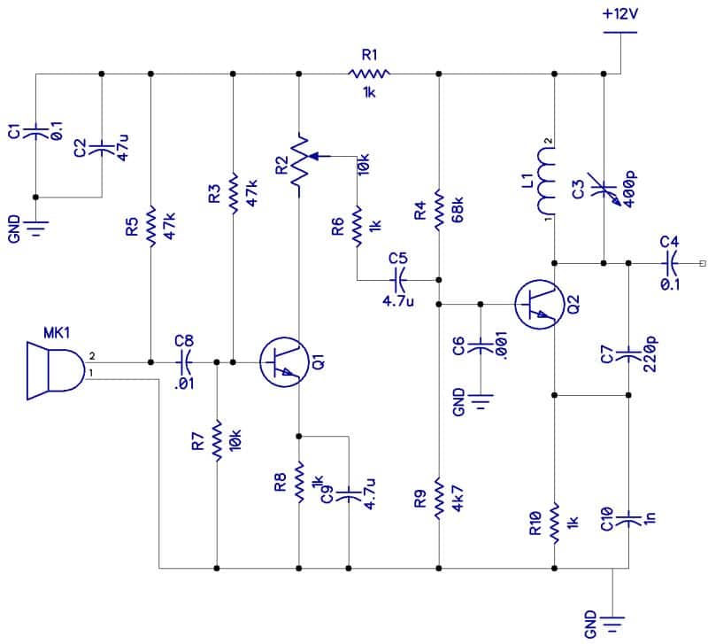
In the circuit above, MK1 is an electret microphone and Q1 is a transistor audio amplifier. The power supply is 12V DC.
Potentiometer R2 sets the drive level, which modulates the base of Q2, affecting the collector current. Transistor Q2 is a Colpitts oscillator with a tuned circuit on the collector with L1 and C3.
Capacitor C4 connects to an antenna.
Using the AM Transmitter
Speaking into the microphone will broadcast your voice over AM. Audio from another source (like a media player) can be input into the circuit at the wiper pin of potentiometer R2.
This is a very low power AM transmitter, so the signal will probably not be transmitted too far. However, commercial AM stations with 500kW transmitters can cover a few hundred to a few thousand miles in daylight. As the ionosphere “rises” at night time, especially at the higher end of the band, these signals will bounce of ionospheric layers and cover considerably larger, even intercontinental distances.
AM Transmitter Antennas
The simplest antenna would be an end-fed quarter wavelength of wire as high as possible fed against a good ground. A quarter-wave has a low impedance at its feed point, providing a reasonable match to the transmitter.
The antenna can be made from antenna wire. To calculate the length (L) of the antenna, use the equation L = 300/f(Mhz).
So for 1 MHz:
L = 300 / 1 MHz
L = 300 meters
One quarter wavelength of L would be:
300 meters / 4 = 75 meters.
Rather long indeed! Commercial AM stations have antennas covering several acres of land, often on towers hundreds of feet high.
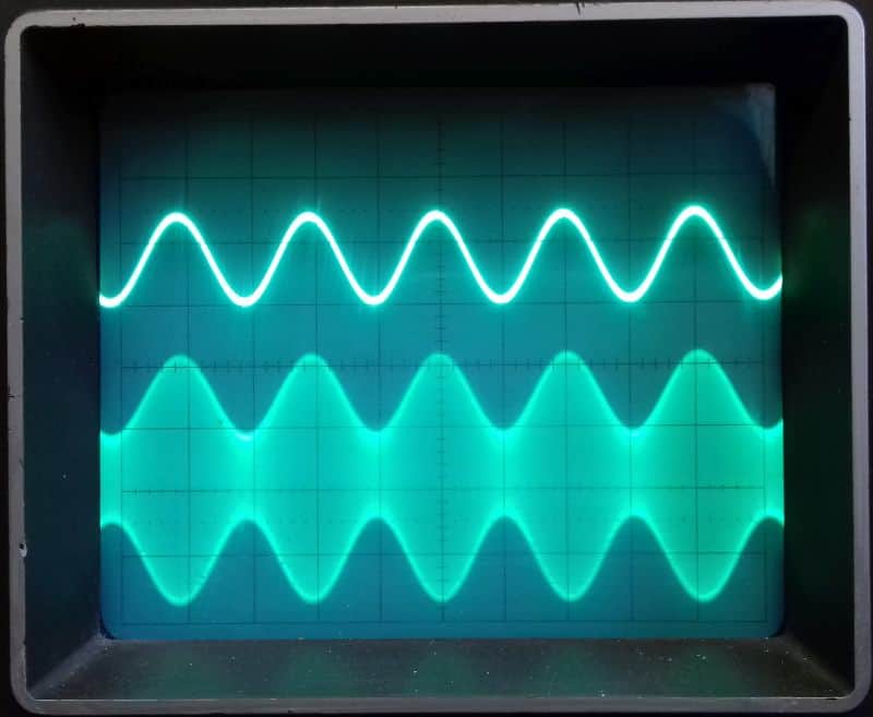
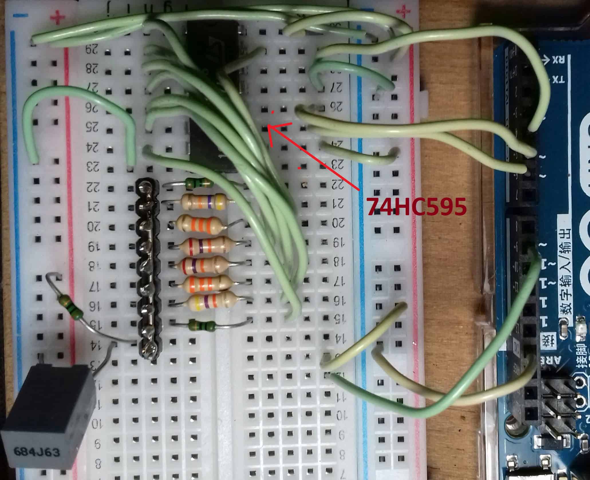
I made a quick lash-up of this circuit to see if it works, and the results are shown below:
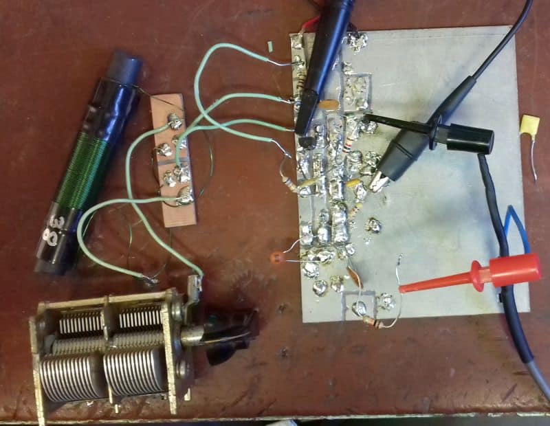 | 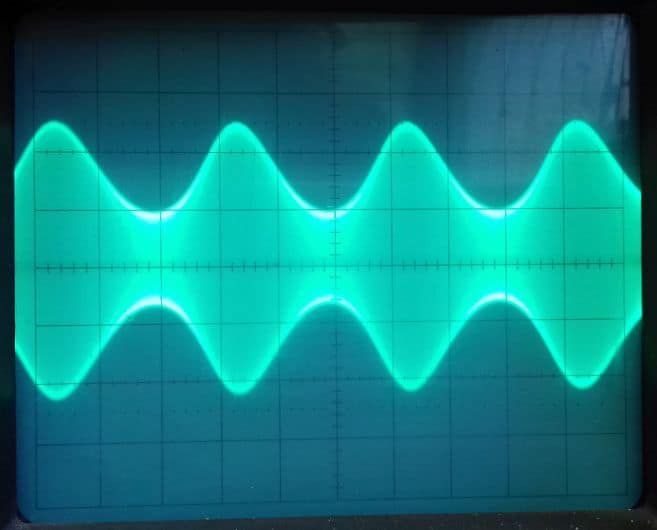 |
| Lash-up of transmitter | Output waveform |
Thanks for reading! Be sure to leave a comment below if you have any questions!


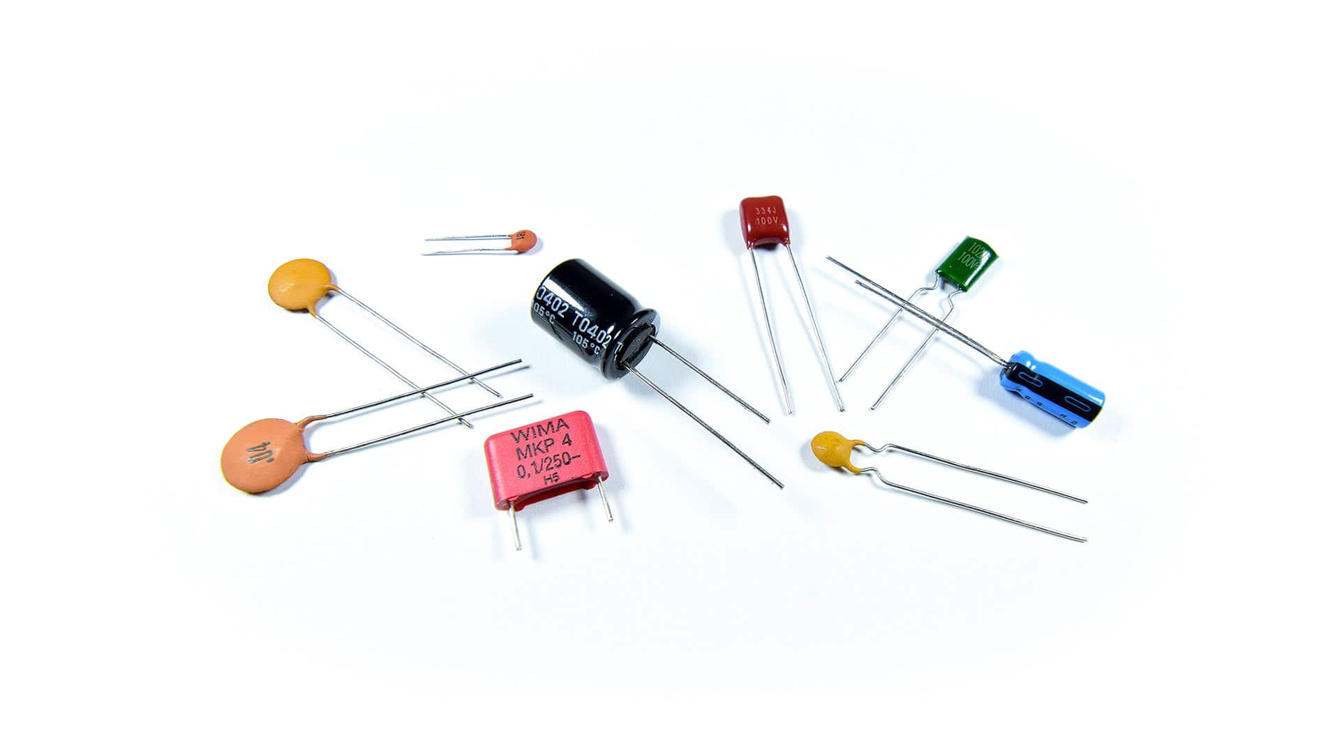
Could you provide the list of details on which components you chose? I know you mentioned transistors, but there are some capacitors that I don’t know if they are electrolytic or ceramic or other, and I don’t know exactly which transistor model to pick. And also the antenna coil. How big should that be? If you could just list the components you used that’d be great. Thanks for the circuit and the help!! 😀
Could you provide the list of details on which components you chose? I can see the materials but please specify the transistor’s and the value of inductance of the inductor.
Hi, I tried to simulate your circuit but I cannot find any 0.1F for C1 and C4. Let say I want to use smaller capacitor, do you have any suggestion? TQ so much