One of the most useful things you can do with an Arduino is use it to control higher voltage electronic devices. Any device you normally plug into a wall outlet can be activated by a sensor or controlled in other ways with the Arduino. The possibilities are endless considering the variety of sensors and modules available to us today.
In this tutorial, we’ll be using a 5V relay to switch the current to a power outlet on and off. We’ll use the Arduino and a sensor to control when the relay switches. To learn more about the 5V relay and it’s different modes of operation, see our article “How to Set Up a 5V Relay on the Arduino“.
We could always wire the relay directly to the device we want to control, but it’s more practical to go one step closer to the source and switch the power at the outlet. That way you can use it for multiple devices without having to re-wire the relay or cut into the device’s power supply. In this project, we’ll connect a power outlet box to a grounded extension cord and install a 5V relay inside the box so we can control it with the Arduino.
Building the Arduino Controlled Power Outlet
WARNING!! – THIS PROJECT INVOLVES WORKING WITH HIGH VOLTAGES THAT CAN CAUSE SERIOUS INJURY, DEATH, AND/OR SET YOUR HOUSE ON FIRE. PLEASE PROCEED WITH CAUTION, AND ALWAYS MAKE SURE CIRCUITS ARE UN-PLUGGED BEFORE WORKING ON THEM.
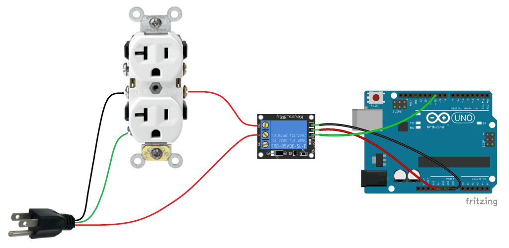
We will install the 5V relay in-line with the positive (hot) wire of the 120-240V power outlet in the normally open configuration. The negative (neutral) wire and the ground wire will be connected directly from the power cord to the outlet. The 5V relay will turn on the current to the outlet whenever it receives a 5V signal from the Arduino.
Here’s a diagram that outlines the connections:
Gather the Parts
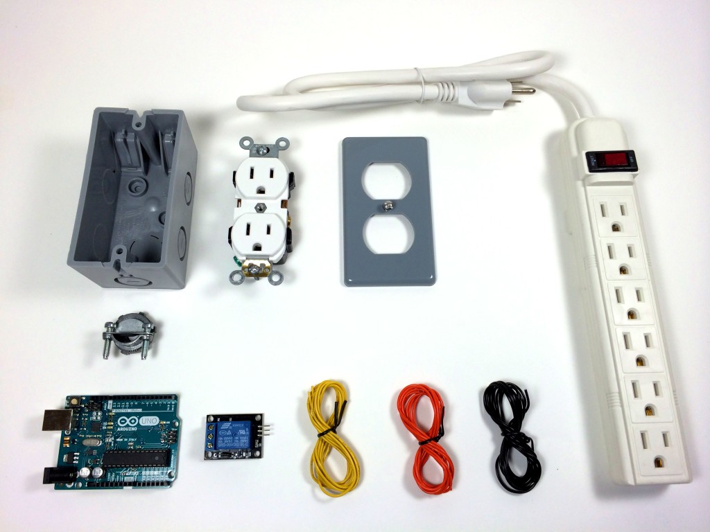
The parts I used are listed below, but you can use other types. This is just what I found at my local Home Depot. I’ve included links to these parts on Amazon so you can get an idea of what they cost, but I got everything (except the Arduino) for under $22.00 USD.
- Arduino UNO R3
- SRD-05VDC-SL-C 5V Relay
- Electrical Outlet Box
- Electrical Outlet
- Electrical Outlet Box Cover Plate
- 3/8″ NM/SE Connector
- Power Strip
- Signal, Vcc, and Ground Wires
Constructing the Box
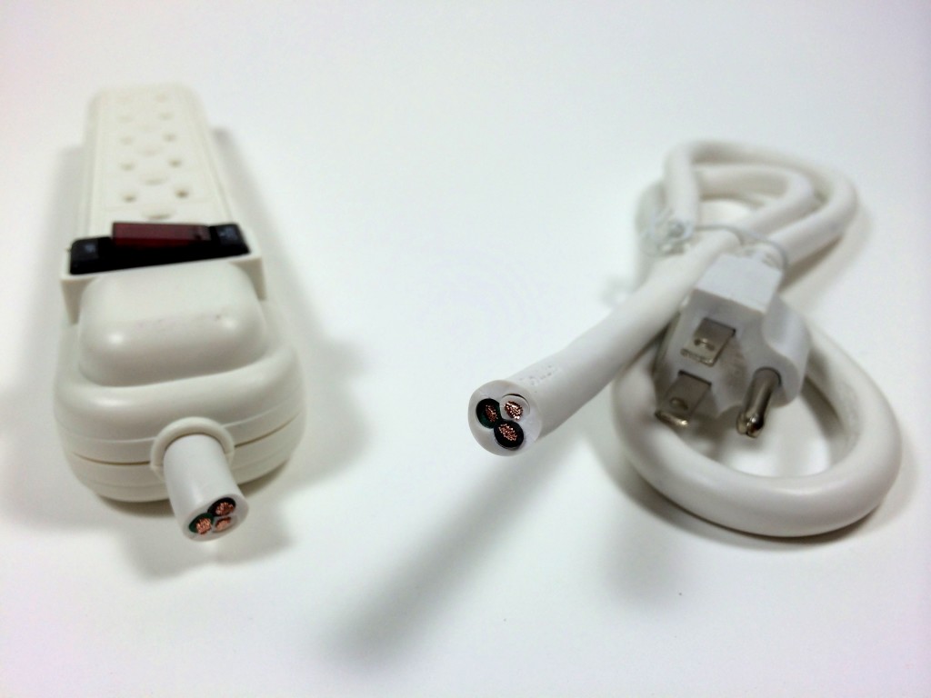
Cut the cord on the power strip and determine which wire connects to each prong on the plug with a homemade continuity tester. My cord has three wires. The neutral (white) wire is connected to the larger prong, the hot (black) wire is connected to the smaller prong, and the ground (green) wire is connected to the round prong:
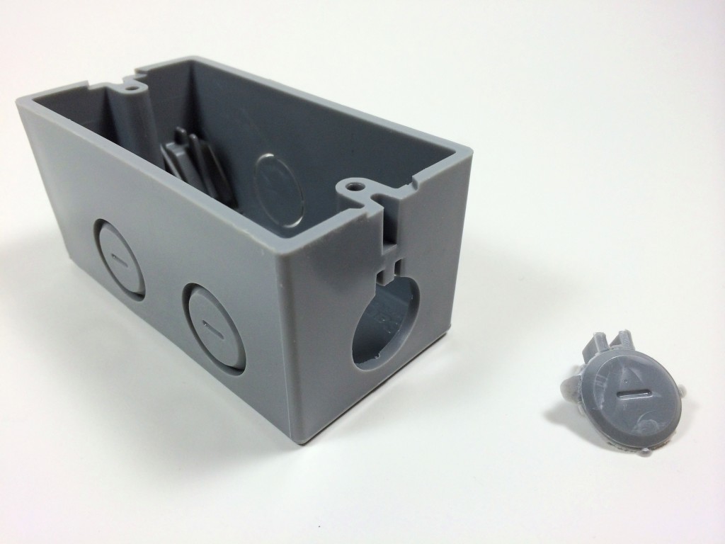
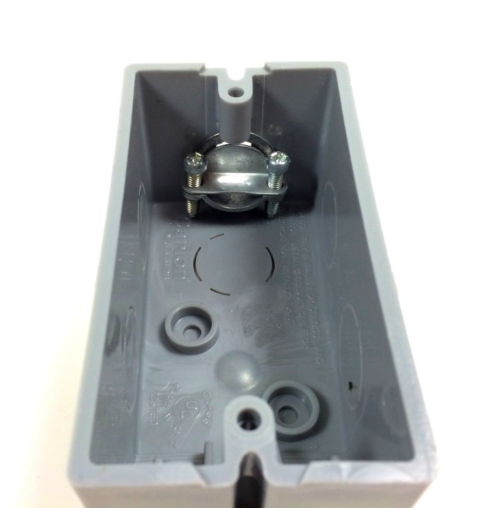
Remove one of the knock out plugs from the electrical outlet box:
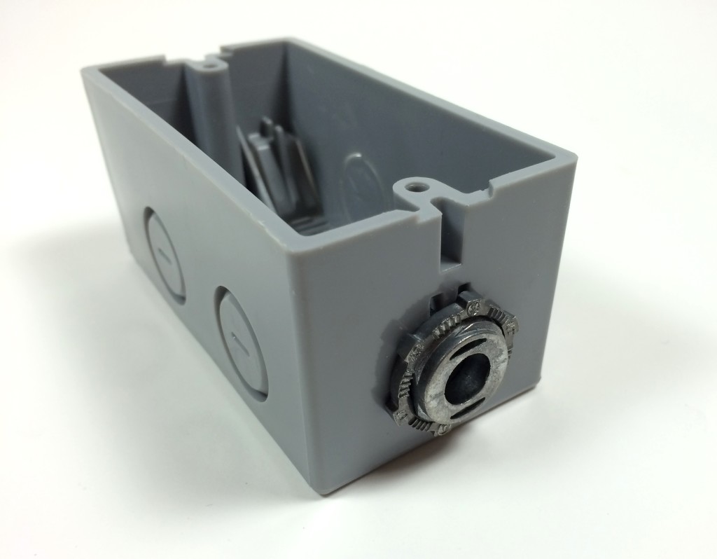
Install the NM/SE Connector:
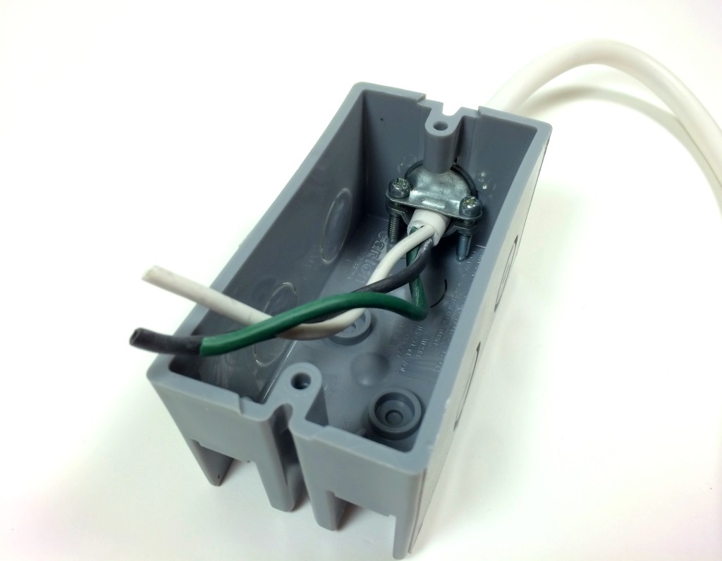
Remove about 3 to 4 inches of the outer plastic sheathing from the electrical cord, then feed it into the box through the NM/SE connector:
Wiring the Relay
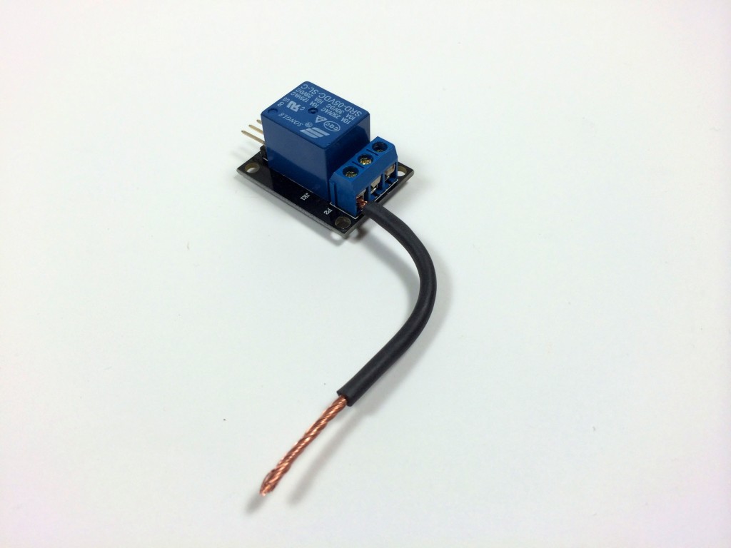
Cut a 4 inch piece of the hot wire and strip off about 1/4 inch of the insulation. Insert it into the NO terminal of the relay and tighten the screw on the relay terminal to make a secure connection. Now is a good time to strip the other end of this wire so we can connect it to the electrical outlet later:
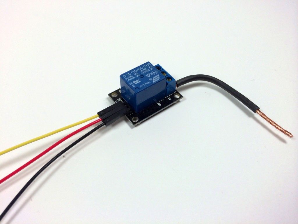
Connect the signal, Vcc, and ground wires to the relay:
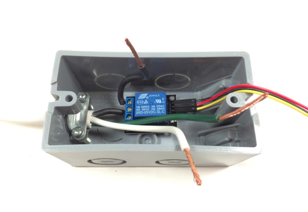
Strip the neutral and ground wires on the electrical cord so they have about 3/4 inch of exposed copper. We’ll connect these to the power outlet later. The hot wire only needs about 1/4 inch since it will be inserted into the C terminal of the relay:
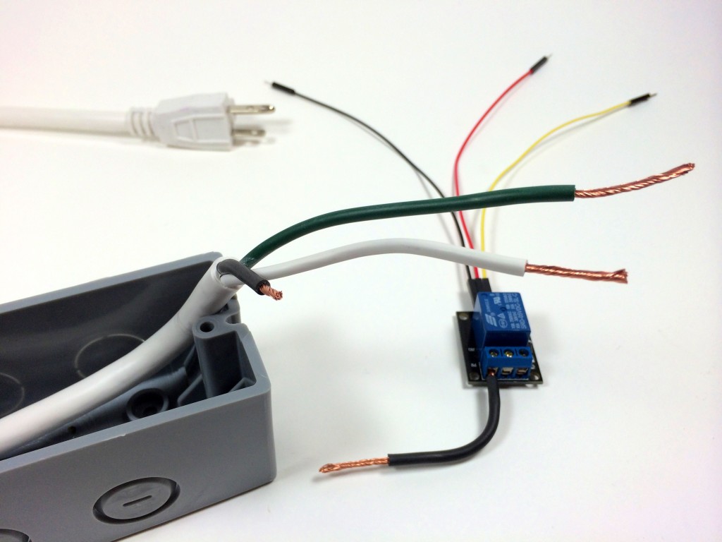
Insert the hot wire from the electrical cord into the common (C) terminal of the relay. Double check that both terminals of the relay are securely screwed down:
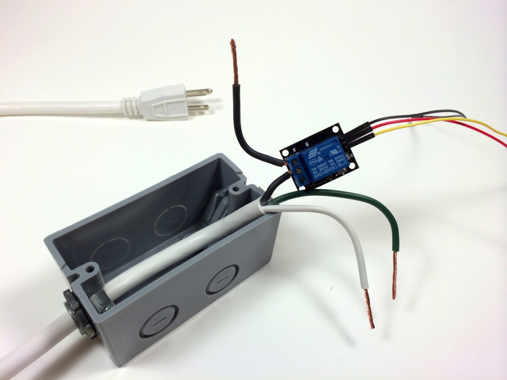
Connecting the Hot, Neutral, and Ground Wires to the Electrical Outlet
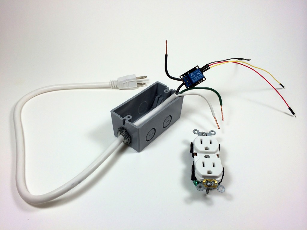
The right side of the power outlet with the smaller slot is the hot side of the outlet. The hot (black) wire from the NO terminal of the relay will be screwed to the hot terminal with one of the gold colored screws:
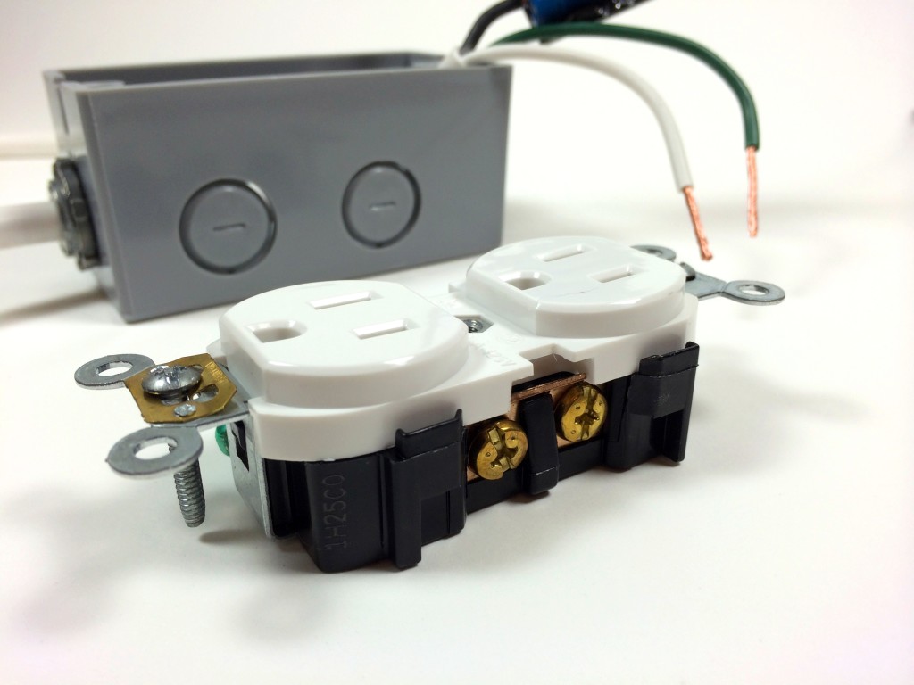
The left side of the outlet with the larger slot is the neutral side. The neutral (white) wire from the power cord will be screwed to the neutral terminal with one of the silver colored screws:
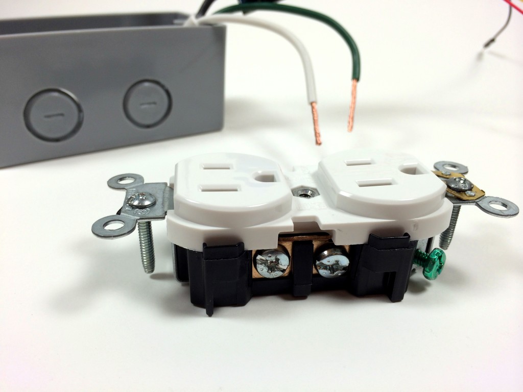
The D shaped slots are for the ground prong. The ground (green) wire from the power cord will be screwed to the ground terminal with the green screw:
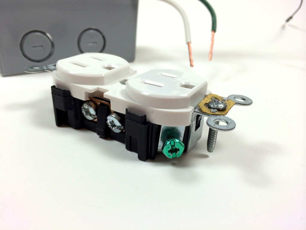
Before connecting the wires to the outlet, position the relay and all of the wires inside the box to make sure it fits well. Now is a good time to trim the wires and tighten the screws on the NM/SE connector:
Now connect the ground wire to the ground terminal of the outlet:
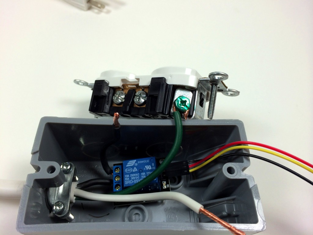
Connect the neutral wire to the neutral terminal of the outlet:
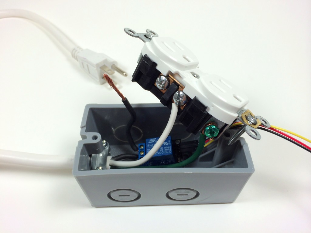
Connect the hot wire from the relay to the hot terminal of the outlet:
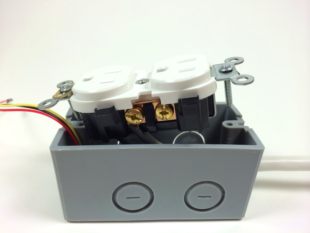
Now that all of the electrical connections have been made we can screw the outlet into place in the electrical outlet box:
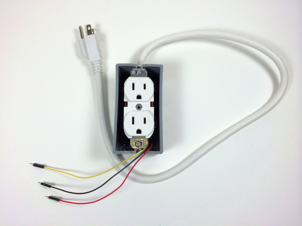
Attach the electrical box cover plate:
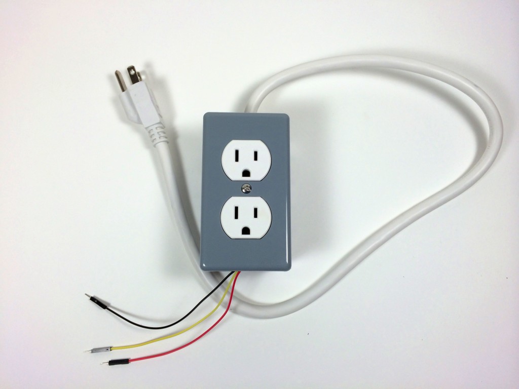
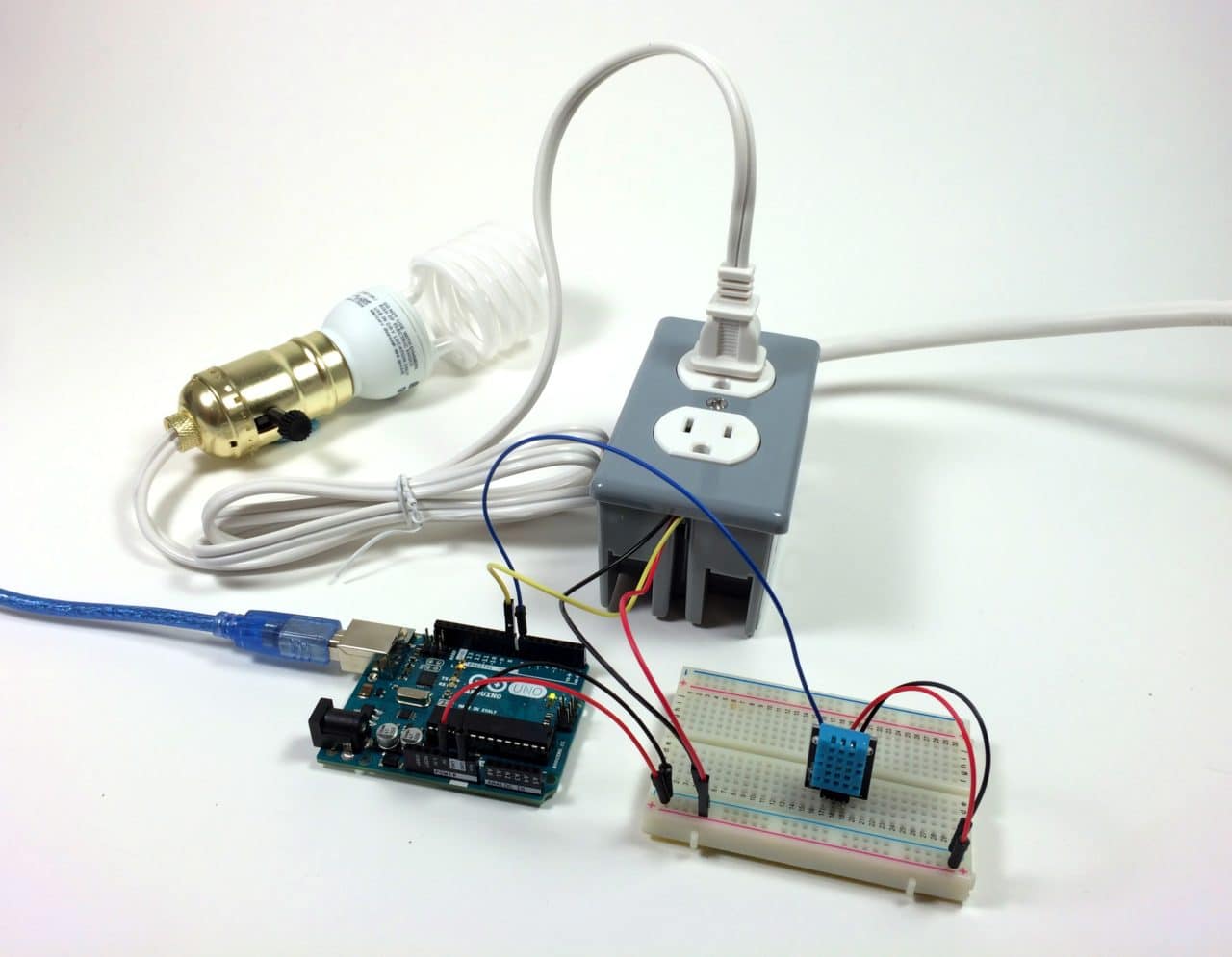
And we’re done. Now we have a 120V electrical outlet that can be controlled by an Arduino. Everything looks clean, and the relay control wires are ready for a breadboard:
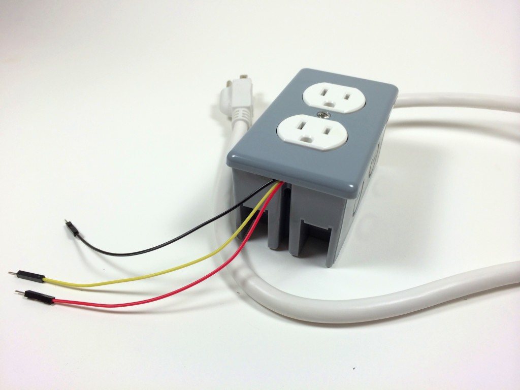
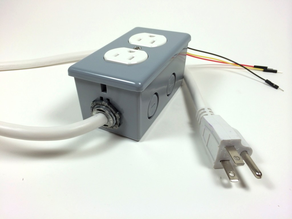
Testing it Out
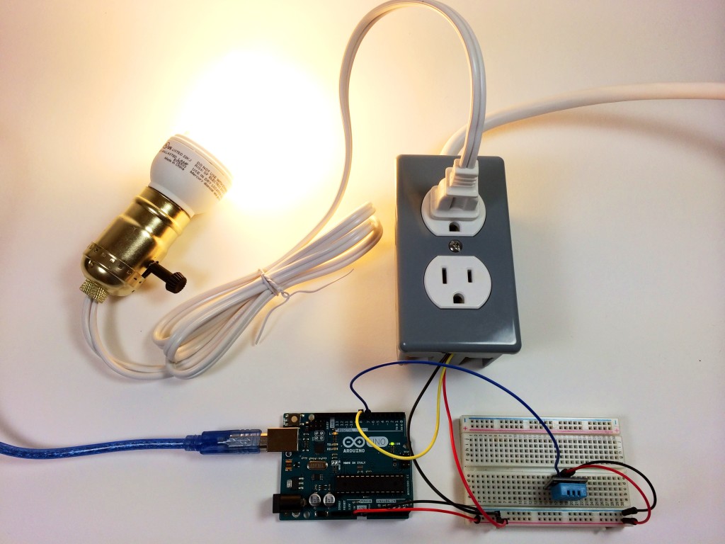
Let’s test out the Arduino controlled power outlet by programming a light fixture to turn off when the humidity gets above a certain point. To make this circuit you’ll need a DHT11 humidity and temperature sensor.
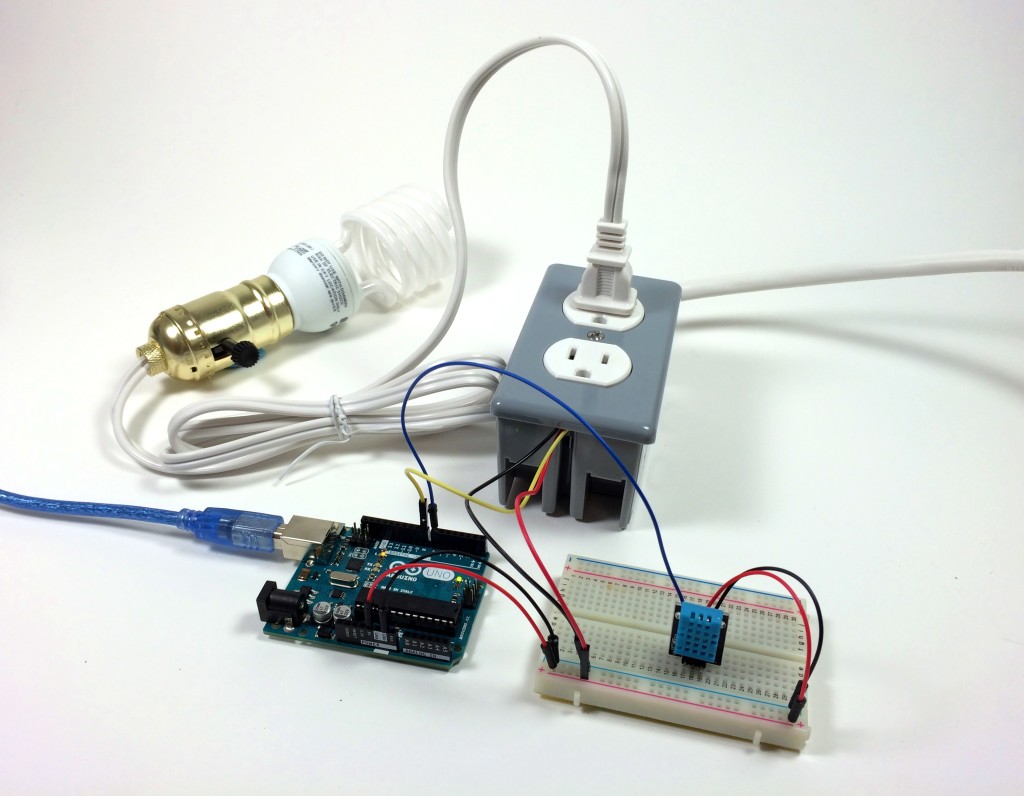
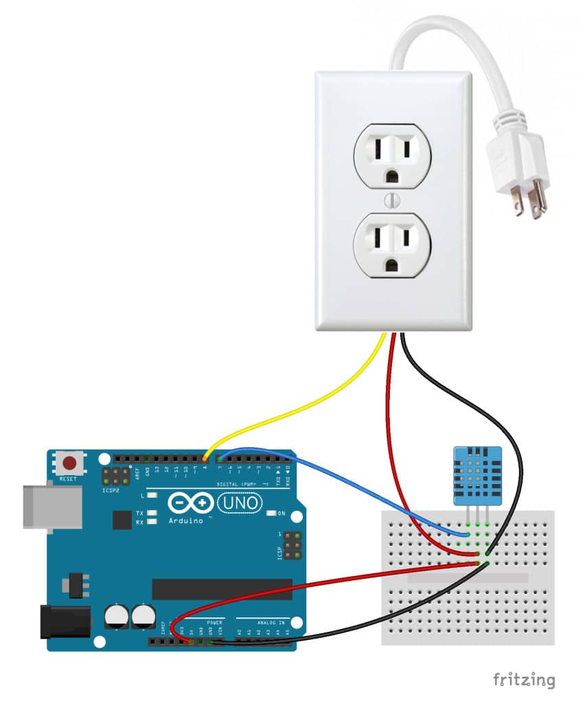
Connecting the Arduino
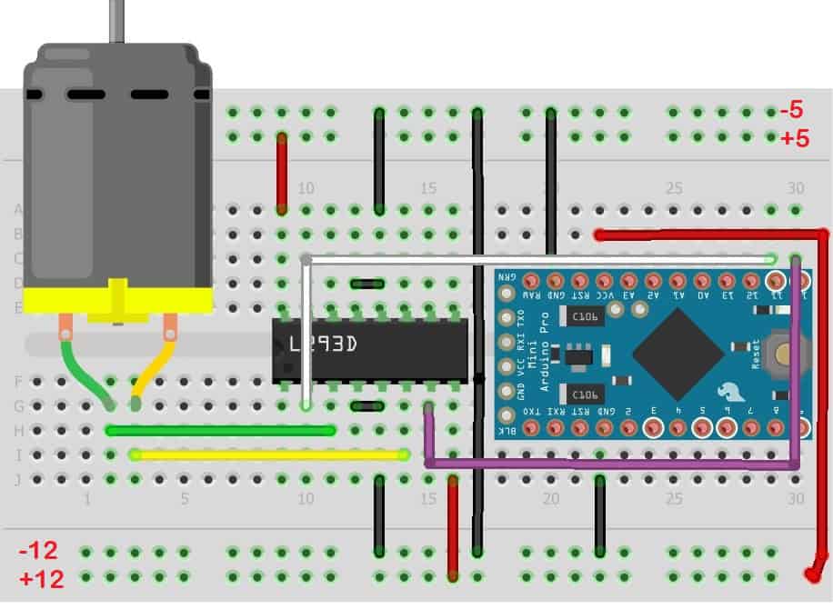
Follow this diagram to make the connections:
Programming the Arduino
After making all of the connections, we’re ready to program the Arduino. Upload this program to the board to control the outlet with the DHT11:
#include <dht.h>

dht DHT;

#define DHT11_PIN 7
int pinOut = 8;

void setup(){
  Serial.begin(9600);
  pinMode(8, OUTPUT);
}

void loop()
{
  int chk = DHT.read11(DHT11_PIN);
  Serial.print("Temperature = ");
  Serial.println(DHT.temperature);
  Serial.print("Humidity = ");
  Serial.println(DHT.humidity);
  if (DHT.humidity <= 40){
    digitalWrite(pinOut, HIGH);
  }
  else {
    digitalWrite(pinOut, LOW);
  }
  delay(500);
}
This program takes the humidity data output by the DHT11 and tells the Arduino to output a HIGH signal at pin 8 until the humidity reaches 40% or greater. Therefore, the light bulb will be on below 40% relative humidity. If the humidity goes above 40%, the program tells the Arduino to output a LOW signal at pin 8, and the light bulb will be switched off.
You can change the humidity at which the relay turns on and off in line 20, where it says if (DHT.humidity <= 40){. You can also use the temperature data instead of the humidity (or use both) by changing DHT.humidity to DHT.temperature.
Thanks for reading! This has probably been one of the most useful things I’ve built so far. You should definitely build one for yourself, especially if you’re interested in controlling devices around your home. Let me know in the comments if you have any questions about this project, and be sure to share it if you know someone else that might enjoy it too!


Just a simple 5V or 12V relay is enough to achieve this TECH…
Exit status 1 !
There is problem in the bord
How is the Arduino getting power here? Is it taking it off pin 8, or does it need battery or a USB cord to stay powered? Also, thanks for this awesome tutorial!
Hey, I just wanted to let you know that I really enjoy and benefit from your projects! I think you have done a great job laying things out in a step by step manner that doesn’t miss anything, which makes it much easier to learn and follow along. Great job NOT leaving out any necessary bits of info!!! Keep up the good work, and I hope to see more your stuff in the future. Thanks!
Thanks a lot! I try to make sure to include everything necessary to set up a project, but let me know if I miss anything or if something doesn’t work!
HI im hving problem with the coding. when i want to verify, it says erorr compiling.
“Arduino: 1.6.5 (Windows 7), Board: “Arduino/Genuino Uno”
sketch_aug24b.ino:1:17: fatal error: dht.h: No such file or directory
compilation terminated.
Error compiling.
This report would have more information with
“Show verbose output during compilation”
enabled in File > Preferences.”
how do i solve this?
That means that the file “dht.h” on line 17 you are calling doesn’t exist or you don’t have it in the folder.
thanks for responding again Ben.
i wanna make the lights off if i blow the sensor.
can put this on line 20 in the coding.
“if (DHT.humidity = 57){ // RELAY TURNS OFF ”
is it right? because it doesnt work after i upload it on board.
There is no button to reply to you so I’ll reply here.
Basically if you need that file, it’s just an import file, then you can remove the line. If u need it then you have to keep it.
thankyou for responding. Do you have any idea on how to solve this? your help is really appreciated.
hello leveraging your project may indicate how to install other rele temperature
Reley 1 35.5ºc temperature (on 34-35 of 35.5)
Reley 2 humidity 40% (on 35-39 of 40)
greetings
Would an outlet like this work triggering an aquarium water pump running at like 4 or possibly 15 W ?
Yeah it would… You can use any sensor to trigger the relay, I just used a DHT11 as an example
I love the article but just had a question. Seems to be a weird senerio…
So I believe everything is hooked up correctly, but I have a GFCI outlet and the reset engages every time the signal gets sent. So if I start with the 5v pin out, as soon as it starts to go in, I blow the outlet. Same with the 8 pin.
Any help would be great!
Same for me, the reset engages every time the signal is sent. Did you get a solution for this?
My solution was to just change it to a non GFCI outlet. I never had any problems. I had it plugged into a surg protected outlet anyway.
I assume it was because of spikes of current or something, but not my expertise. But never had problems after switching.
Turn off arduino, unplug outlet. Plug in pins, then plugin arduino and outlet. Does that work?
I prefer to use a solid state relay. Easier and beefier.
thanks for this
Beware: 240V in most American homes is available as the voltage between (2) 120V “hot” phases (wires); interrupting only one of them means that the other remains “hot”, and potentially lethal, at the load–even when it’s “off.”
Instead, use a DPDT breaker, something like this:
http://electronicsure.ondatasheet.com/FTR-F1.pdf
to interrupt bofth the hot legs.
Or websearch this (which today led me to ebay.ca):
5V 2 Channel Relay Module Shield For Arduino ARM PIC AVR DSP MCU Electronic F5
Then follow the instructions above, using one channel for each leg.
Good job. everything (even these chats) was helpful. great. THANK YOU VERY MUCH..
Hi.Tanx for all your help. My problem is with the sketch. Where can i find dht.h library?
https://codeload.github.com/markruys/arduino-DHT/zip/master
Does this just connect one if the outlets to the Arduino? Is it possible to split the hot wire and run it through a two channel switch to control each outlet separately? Thank you for the tutorial it looks great!
Yes, I actually did this at home. It was super fun. One control for top, one control for bottom, one for both together.
I just ran a hot wire and split it two two using a wire nut and ran one wire into each relay (two relay module). Then one wire going to top, one wire to bottom.
You do have to break the copper bridge in between the top and bottom on the side of the outlet. I am not sure how much you know about electrical, but I learned at this. So this might not be the best way but it works.
5V Two 2 Channel Relay Module With optocoupler Compatible With Arduino PIC AVR DSP ARM by Atomic Market https://www.amazon.com/dp/B00TMFVVG6/ref=cm_sw_r_cp_api_UGO2xbJX0W7WR
Just an example of where you can buy a 2 channel relay.
Hi !
First of all I really loved your article, it was very useful and explicative. Is it possible to adapt this project to control the light switches, I mean I want my lights (those ones that the switches are on the wall) to be smart, and replace those switches with a relay and an Arduino in order to turn on the lights at night. I know the answer is yes but I don’t know pretty much about electrical connections. Thank you in advance.
Dear friend
Thank you for your soooo well explained example.. I just followed it step by step and.. it worked!
I did a couple of pictures and uploaded a post to my own blog https://tontuino.wordpress.com/2016/11/22/enchufe-controlado-mediante-arduino/
Next step: Now i would like to make it work from an smartphone.. :)
Thank you
Thanks for the info! I’m looking to do basically what you have shown except the device I need to power is a little more heavy duty. I would need a relay that has a 5vdc coiled well because I’m using an arduino, but need to power a 240v ac 20amp device. Anyone have a suggestion on a good relay for this ? Thank you.
Use a 5A 110V relay to fire a 110V coil 220V 20A contactor.
https://www.ebay.com/itm/231770174148
Anything like this works. No matter the voltage. It is controlled by 5v but can run high volts through it.
That’s a really illustrative go through for novices such as me into arduino and pi stuff for automation. I was hoping I could bother you with a few questions. I have been wanting to build a cheap water filter for heavy metal remediation and it asks for a time interval based control of a 240 V aquarium air pump to allow periodic pumping of a volume of water through the filtration media. What would be the best possible source to obtain the lay out or instructions for such a similar build illustrating the time based control of a 240 V appliance using arduino/pi?
Can you please write the program for the following temp. and humidity conditions:
The light should be on (i.e. pinOut, HIGH) for
1) RH>=70 AND Temp>=25
2) RH>=70 AND Temp<=25
3) RH=25
While, the light should remain off (i.e. pinOut, LOW) for
1) RH<=70 AND Temp<=25
I am trying to build something similar but instead of turning the appliance on or off I want to vary the current going to it over time. I wanted to use a digital potentiometer connected to a programmed Arduino. What specifications should I look for in the potentiometer? Also is there a better way of varying the current going to an appliance? Do I still need a relay if I’m using a potentiometer? Thanks
Sounds like you might be wanting a dimmer switch for a lamp. Look into using a triac and dtive it with PWM controlled by your pot.
How do I connect the power outlet into an 8 channel 5V DC Relay Board? Is it the same process?
Hey, did you find any info about this?
Hey man, could you find any info?
Sounds like you might be wanting a dimmer switch for a lamp. Look into using a triac and drive it with PWM controlled by your pot.
this is not working.. i changed dht to DHT to match the library name
#include
dht DHT;
#define DHT11_PIN 7
int pinOut = 8;
void setup(){
Serial.begin(9600);
pinMode(8, OUTPUT);
}
void loop()
{
int chk = DHT.read11(DHT11_PIN);
Serial.print(“Temperature = “);
Serial.println(DHT.temperature);
Serial.print(“Humidity = “);
Serial.println(DHT.humidity);
if (DHT.humidity <= 40){
digitalWrite(pinOut, HIGH);
}
else {
digitalWrite(pinOut, LOW);
}
delay(500);
}
Do you fixed it now? Is it working now sir?
Hello,
Am doing a project ; Fingerprint Authenticated Device switcher.
Am trying to use the fingerprint scanner to switch on and off the outputs of my arduino. Meaning;
– Only when i insert my fingerprint, the arduino will be switched on giving access to my bluetooth module in my arduino so that i can access the devices connected to the outputs of the arduino.
– And when i re-insert my fingerprint, the arduino will close or switch off all connections linked to it.
My problem is; i can’t figure out how to write the program to do these tasks.
You’ve got any advice or helpfor me?
How to connect 3 dht11 to arduino in the same time?
Yo your link led me to a scam site. It probably was one of the ads? https://t.co/KEDJXBSWmq
Can I put LCD too??
can you do this? but with a Raspberry PI instead of an Arduino UNO?
Thank you for the guide but 1 major issue above is about powering the Arduino itself. A compact solution would be to use a battery but unless u make it rechargeable, eventually u will need to change it. Another way would be to use an ac-dc adapter connected to 1 of the twin ac sockets above but that has got to be always on instead of being controlled. That can be achieved by using 2 individual sockets and daisy-chaining the Live and Neutral wires accordingly. So you will end up with twin sockets but 1 will always have power (for the Arduino) and the other can be used as a controlled socket for other appliances.
Nice
Hye sir,im just curious why you dont use any step down transformer in that project? Is it okey using arduino without step down transformer?
The project above is not powering the Arduino at all. To do so either an on-circuit or external step down transformer needs to be included.
😍😍😍
Jonas Hansen
This is great! One question, if I were to use an adafruit Itsy Bitsy https://www.adafruit.com/product/3677 how would I be able to leach off the already supplied 110 power to also power the Arduino rather than use another power source?
Thanks!
Besides using an old usb charger?
Can i connect it to my C# program i created in Visual Studio?
Well done , great article well documented, with plenty of pictures, highly detailed and … not skipping on safety. You should become a teacher.
Pls is there an additional file because i am being told that i don’t have a file by name dht.h and i should try and get that file . Due to this, i keep on receiving an error message
hi,
i need help, how to purchase this device for one villa and connect to an electric switch panel. I also looking business level
I am not able to get output due to error in code as it says ‘dht’ does not name a type..how should i proceed now
Even if i changed it to any other thing then i am getting a error in “if” statement such that unexpected token error…
Hi
If I wanted to control 12v led bulbs, could I use the same setup as above except that I need to use a transformer from the actual mains and use the step down output into the electrical switch?
I’m concerned about the power requirements for the transistor. Arduino I/O pins are only rated at 40ma. The relay datasheet (https://www.circuitbasics.com/wp-content/uploads/2015/11/SRD-05VDC-SL-C-Datasheet.pdf) indicates that at 5V VCC, you will need 71.4ma to activate the relay. Seems to me that powering your relay switch directly from the Arduino is a bad idea.
Gosh, nvm. The power pins can source 500ma-1A depending on the power to the Arduino.
You shouldnt put the Low voltage relay inside of that electrical box. It doesnt follow electrical code and can be a fire hazard. I would recomend a double gang high/low voltage box so you would have the Relay in its own compartment.
Hello,
Thank you for putting this together. I’m having trouble with the sketch. While compiling I’m getting the following error: expected primary-expression before ‘.’ token. I’m getting this or lines 15, 17, 19 and 20.
You made the blog becomes useful to every household that deals with the power outlet problem. There are things to consider before doing a DIY. Make sure you know how to fix it before trying it.
Hello, I would like to know if I can do a blink program with a strip of LEDs using this circuit? Thanks
So, what do you do with the unusable power strip, now that its
cord has been amputated? Why not just obtain a cord, and
avoid ruining a perfectly good power strip?
Hey y’all I got everything together except for the temp humidity sensor hooked up. The reason I’m stuck is because my sensor is a 4 pin not a 3.
Can someone help me adapt the code and wiring? I’m fairly new to this
Is there a way for the microcontroller to be able to read the amount of charge (battery charged percent) or (impedance for that nature of determining charge left) in an iPhone battery while plugged into the built outlet through a charging adapter?
Hi! Just a quick clarifying question… does the microcontroller get power from the live wire through the relay? Or is the microcontroller getting power from the micro usb connection
Power to the Arduino should be through USB. Maybe with a suitable USB power pack/mobile charger type that is NOT part of the relay (as the Arduino needs constant power to work to switch on/off the relay). So you have 2 sockets- 1 normal to deliver power and another that is controlled by the Arduino with relay. That being said, it is possible to split the live by using just 1 socket but you would need a step-down transformer to power the Arduino with a lower voltage.
what i need is to be able to power my board from the A/C i am controlling, in the same way that virtually all IOT gadgets are usually powered, in the real world.
nobody seems to be talking about how to do this – am i just not looking in the right place?
any help would be much appreciated.
I have the same question: how is the Arduino getting powered here? By a USB cable? Battery?