At some point in your DIY audio projects, you’re going to need a way to input audio into your circuits. One of the most versatile ways to do that is to use a 3.5 mm stereo audio jack. These can be salvaged from an old set of portable audio headphones. If you cut off the ear buds, you can plug the jack into an audio source and connect the wires directly to your circuits.
In this tutorial, I’ll show you how to wire the two most common types of audio jacks – TRS and TRRS.
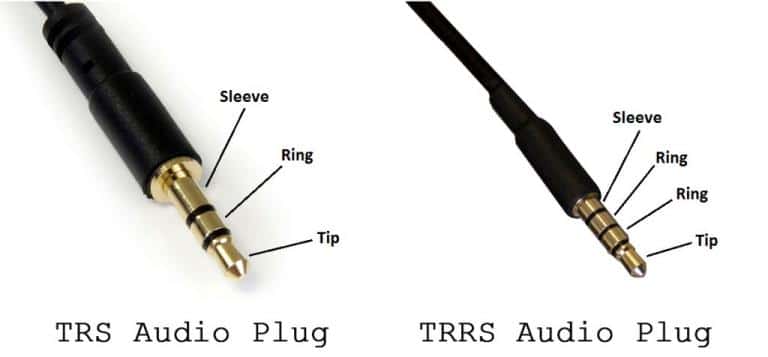
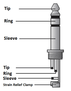
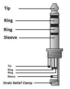
The T stands for “tip”; the R stands for “ring” and the S stands for “sleeve”:
TRS Audio Jack
TRS audio plugs are found on standard stereo headphones that don’t have a microphone. After you cut into the cable, you’ll probably find one of three common ways these can be wired:
- Copper wire ground sheath wrapped around two insulated audio signal wires.
- Two separate insulated wires, each with its own signal wire and a ground wire inside.
- Separate insulated wires for the ground, right audio, and left audio inside a single cable.
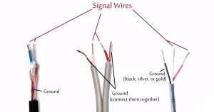
Usually red wires are the right audio channel and blue wires are the left audio channel. Check the image below to see which wires are audio signal wires and which are ground wires in the most common TRS wiring schemes (image courtesy of DIY Perks on YouTube).
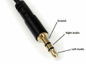
The wires are connected to the TRS plug like this:
Depending on the type of plug, you may have access to the pins inside the connector’s housing. The wires are connected to the pins of the plug like this (image courtesy of Rob Robinette):
If you only need a mono input, the left and right audio channel wires can be connected together.
Once you’ve identified the wires, simply solder them to the correct input channels in your circuit, or attach pin connectors so they can be used in a breadboard.
TRRS Audio Jack
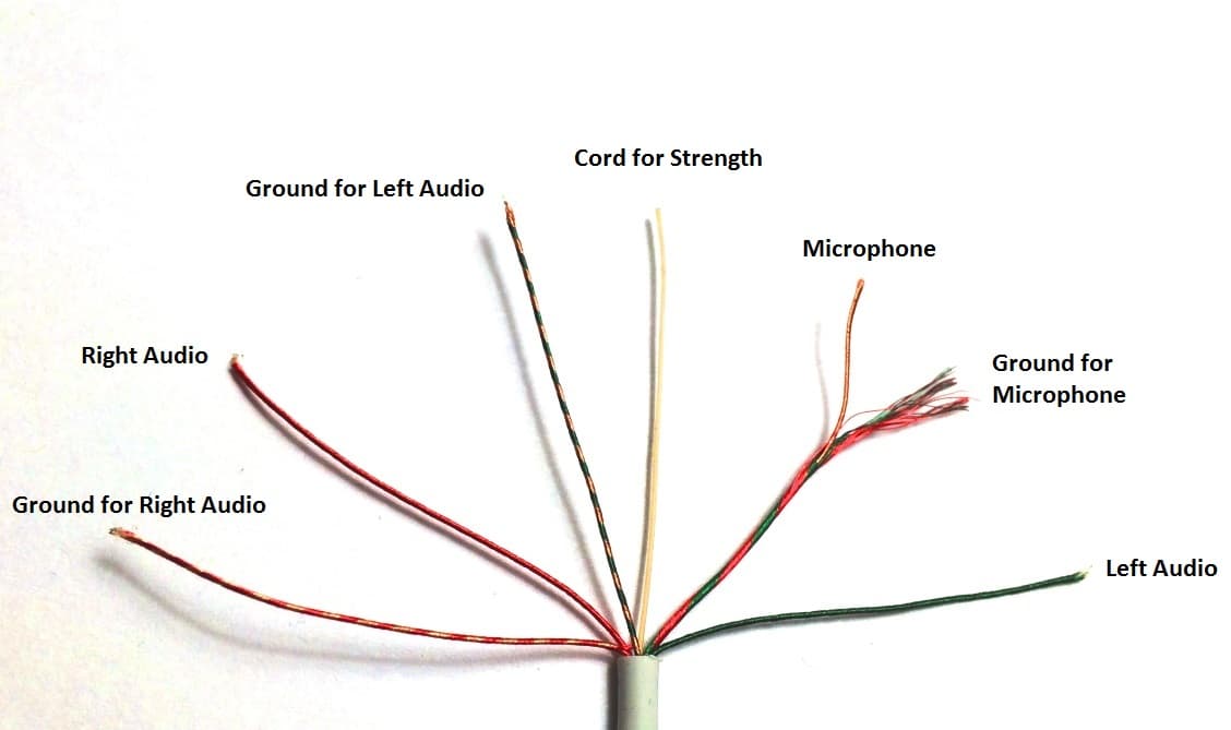
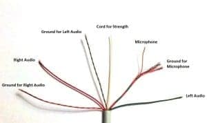
The TRRS audio plug is found on iPhone headphones and other headphones that have a microphone. After you cut open the plastic insulating sheath you’ll find 5 separate wires:
- Solid red wire: right audio channel signal
- Red and copper twisted wire: ground for the right audio channel
- Solid green wire: left audio channel signal
- Green and copper twisted wire: ground for the left audio channel
- Red and green sheath with a copper wire inside: Inner copper wire is the microphone signal, outer sheath is the microphone ground.
You’ll also find a plastic cord that’s used to strengthen the headphone cable:
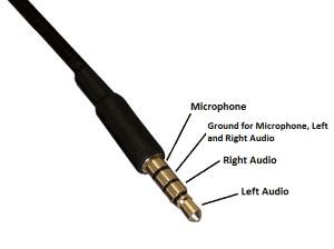
The TRRS plug connects to the wires like this:
If you can get to the pins inside the plug’s housing, the pins of the TRRS plug connect like this:
If you only need a mono audio input with the TRRS connector, you can combine the combine the red and green wires to make a single mono audio wire, then combine the ground wires to make a single ground wire.
There’s a very thin coating of insulating material on each wire, which is how they can be bundled together without any plastic insulation. Before soldering or connecting them to anything conductive, run a flame over the wires quickly to burn off the insulation, then wipe clean.
Once you’ve done that, the wires can be soldered directly to the inputs on your PCB, or connected to jumper wire pins so they can be inserted into a breadboard.


Good stuff…thanks
Your welcome, thank you!
Ahh , a very good knowledgeful page . It helps me a lot😊☺
hi.. need help.. i was using skullcandy cusher wireless and my dog chewed on the headband and the wire got damaged.. i dont know the name of the wire and wjere to get it from. its an 11 wire cable. can any one help me.. atleast tell me the type of cable.
thanks
Good u projects
I have a broken headphone (an TRRS) I accidently bought a TRS plug, wil this work?
I dont use the mic at all so I was wondering if I solder the TRRS cable on a TRS plug will it work?
thanks in advance
yeah, i think so:)
With this plug you can only get mono as explained in the article – you connect the wires from both sides and them connect them to the ring. The sleeve is for input so you can’t get an output signal from it.
yes, of course, you just wanna connect the “right audio wire” to both ring in your TRRS plug. That should do the trick
You misread his question – he got a TRS plug… Answer: with this plug you can only get mono as explained in the article – you connect the wires from both sides and them connect them to the ring. The sleeve is for input so you can’t get an output signal from it.
This answer is wrong. TRS plugs supply stereo audio. (TS supplies mono.) The tip is left, the ring is right and the sheath is common/ground. The answer is, yes you can. You will just have no place to connect the microphone signal from the TRRS wiring in the TRS plug, so you will lose the function of the microphone but will still have stereo audio, as you correctly surmised. (All 3 plug types are compatible with a TRRS socket, and will conduct the channels the respective plug type is meant to.)
Sorry, I just realized your answer was for another question :D
I picked up the supplies at Radioshack to make the audio amplifier circuit. I ended up buying a mono audio cable before I realized you had used a TRS cable. I was trying to combine this project with another popular project, sending audio using a laser. I have the audio transformer and the laser set up to be my transmitter but instead of picking up the signal and throwing it to an amplified speaker, I wanted to make my own amplifier. Is this just wishful thinking on my part? Could the input signal be replaced with a photo resistor with the changing laser light or does this circuit require the TRS or TRRS in order to work? Could using a mono audio cable work too?
Hello i have beats urbeats headphone
I want to the wire layout for trrs plug
It has 5 wires
Red
Green
Red gold
Green gold
Gold
And a white wire in between some wires dont know which please help me
Hi, have you managed to get these details?
Same issue here. Did you ever find out? Im guessing the white cord is the mic.
Different headphones have different colour coding scheme for wires ,it is preferrable to use a multimeter to test connections. find the ground then left right audio and the last one will be the microphone. remember the L R will serve as positive +. and ground will be negative -, common for all.
how to connect two wired mic red and white into audio jack 3.5 ?
This is good information! Thanks! What can i do to really give thanks?
Very good info. Too bad all questions can’t be answered this well
Ok. I’ve looked trough the article. However just to be on the safe side I’d like to ask:
How do I proceed when I have “dismantled” a hands-free/headphones set and found myself looking at wires* of these colors – Green; Blue; Copper; Red.
The order in witch they have been soldered is as I’ve listed them. From the furthest, smallest “ring” – Green, Middle – Blue, 3th is Copper and finally the red wire is soldered to a ring that seems to be the same as the one depicted in the article as “Sleeve”. Only here there is just a 1by1 mm elevation acting as ending of the jack section.
Here is a surprise: there is also one more copper wire standing unattached and by all accounts I think it must have came off the ring with the other Copper. . .
Can you show me if possible how to make a c port headphone adapter using the female side of a trs ( 3 wire) cord attached to a c port cord? I don’t need the mic I’m just looking for audio…PLEASE. I have a Samsung s20 ultra and I’m not I’m a soon situation to be able to be the real deal.. please help.. thanks!
Hi,
I am trying to repair a headset with microphone. There are two separate cables, glued together but physically separate.
In the right cable (where the microphone is) I find: red, blue and copper wires
In the left cable I find: green and copper wires
It looks likely that the green and red are left and right audio respectively like in your photo of a standard, 1-cable TTRS. Then it would be quite logical for the two copper wires to be masses, it would follow that the blue wire is the microphone. Could anyone confirm that ?
Thanks !
In my Samsung galaxy grand neo my mic is not working because it has a small crack on motherbord can I conect mic with earphone jack. Please tell.
Here is how to convert TRRS to TRS without anything. First i want to say that TRRS pins are not always the same, i mean, the pins you mentioned above is an iPhone pins (Left, Right, Ground, Mic), and Nokia (and most headphone out there) pins are Left, Right, Mic, Ground. This method is only tested on (let say) Nokia headphone. To make sure that you have Nokia headphone, just plug your headphone to an android device or Nokia device and make sure its work.
Okay, so when I plug the headphone half-way on my laptop, i can hear the normal sounds, and the mic is work as well. But, when plug it all the way in, you can’t get the mic works, and the sound is horrible. Here is my solution, first you need to open the “control” plastic (the dial-up button,etc). You can see there are a mic and the button that you push everytime to make the sound good. On that button, let say there are 4 pins, 2 pins are already connected with cables. Your job is to connect the other 2 pins using lead. And that is how it work.
The second way… if your headphone control is using a mini circuit-board, you can use a tape to keep the button pressed (but sometime the mic is not working and No-Stereo || you can do an experiment).
If you can’t understand what I’m saying, sorry, I’m not an english speakers xD
oh yea, i think iPhone headphone should work on laptop without problem. Nokia’s mic is on trRs, and work if i plug it half-way. iPhone’s mic is on trrS. Just my opinion.
I have sharper image headphones with wires copper green blue and one which is copper+Green color. Please tell me which are the negative and ground terminals etc
thanks for share knoledge
The diagram for the TRRS plug has the mic and ground labelled incorrectly. The as a rule the sleeve is usually the ground, 1st ring control or mic, 2nd ring right audio, tip left audio. All ground wire can be soldered together to the sleeve
What is the difference between the grounds for the mic, and left and audio channels?
Thanks for the info!
thank you circuit basics this helps me a lot.
Just remember, on the TRRS for iPhones and other phones are wired differently. iPhones go left, right, ground, mic. Most others go left, right, mic, ground. They sell adapter cables that swap the mic and ground so you can use a headset that is wired one way with a phone that is wired the other way.
Hi..
Im trying to connect my (already cut) JBL T300APURE BASS(TRRS) to an ASUS ZENFONE2 HEADPHONE (TRRS) plug,but I CANT make it work.Need a little help please. ????
Here are their respective wiring:
JBL(split type cable)> LEFT WIRE-RED,BLUE,WHITE,COPPER
RIGHT WIRE- (another)RED,GREEN
ASUS(round cable)> RED,GREEN,WHITE,COPPER
THANKS IN ADVANCE CIRCUIT BASICS ????
I have a trrs but Idk how to connect it I have a blue wire a red wire a green wire and a copper wire
Can you mention which colour of the wire is left right ground and mic?
I find it interesting that the Raspberry Pi uses the sleeve for video out instead of microphone input. Be careful with your pin outs.
My headphone has 6 insulated wires,- red, blue, green, yellow, white, and black… Please what’s the configuration.?
My Laptop has a TRRS connection. I want to make a adapter where the audio out is feed back to the mic to record webinars. Could i Solder the grounds together and solder a loop from the left right audio to the mic pin?
I have a LG earphone and it’s trss plug is not working as (wires are lose and when I this the wires closer from.the plug it starts working) so I removed the wires and separated the plug now I don’t know how to solder them and the previous plug.I have a dark purple, pink,green,red green,2 blue,three copper 1 is thicker, and a red wire.how do I solder them
Thaks 4 dygaram. I like uvr dyagram.
I want. Colour wire red.. couper..blue..green
Finally, someone actually posted this schematics in a decent manner. Thank you so much, although it made me swear anyway because my headset have reversed colors for left and right (no, I’m not mistaken, I had to purposely connect them wrong), no idea why but at least it works.
Thank you, have a nice day :)
I have the pilot lighting blue male aux cord that has bluetooth, charging port, and power in and off . The wire got cut some how. How do you wire it up to make a single line male aux cord and it will still light up blue?
I am wanting to replace a dmx controller’s mic with.a line in anything i should know or can i just remove the mic and install the audio jack.
Hi. How do I tight a jack aux cable to a 30 pin apple cable ?
The 30 pin apple cable is connected to the back of my car stereo and it has 8 little cables, the white one (down bellow) has 3. Would you please help me to connect them so I can play music from Iphone thru the car speakers?
Hey your projects are awesome, do you have anything like turning your remote control into a computer mouse kinda things?
very good i extremly looking for it
thank you
Good guidance for repairing old headphones, thanks
Thanks for providing such great help to everyone!
Just FYI, the ‘cord for strength’ in your image is actually what you use to split the sheath down to access the individual wires. You pull the nylon cord down against the sheath and it splits it right open. They provide the same cord in many multi-pair cables ranging from 4 pair LAN-type cables to large 25 or 50 pair cables.
Again, just FYI – and thanks for being awesome!
My headphone has 6 insulated wires,- red, blue, green, yellow, white, and black… Pls what’s the configuration.?
Usually when we connect a 3.5 mm extension, the speaker output audio gets routed to the extension automatically. But do extension cables exist where audio is routed only when a speaker is plugged at the female end, means when a speaker is not connected to the female end of the extension cable, the audio should be played on the usual speakers only
JACK and PLUG are not interchangeable terms. What you are describing is hacking a headphone PLUG. The JACK is what it plugs into on the receiver, phone, etc.
Otherwise, a very well done article.
Nice post.
3151LT Flange Mount Differential Pressure Transmitter-Level Measurement
https://www.china-transmitters.com/pressure-transmitter/flange-mount-pressure-transmitters/3151lt-flange-mount-differential-pressure.html
The 3151 series of transmitters,
is Huaheng’s most recent evolution of the DPharp family of pressure transmitters.
What about a single earpiece and microphone with a TRRS plug? Is one of the rings not used?
Great article around a common set of problems with evolving tech. Standardization would help , but basic continuity measurements solve all.
So I want to use my IPhone earbuds on my Xbox and use the mic. You can’t use the mic because the ground is in the wrong spot for Xbox. If I switch the ground around, will it work? I really love my earbuds and I wish I can use them for gamechat on Xbox. Help me out! Thanks!
Help needed.
Removing action camera mic , mic is connected by the + & – terminals on its circuit board.
Going to connect a wired 3.5mm female jack that will be left outside the case, this will allow me to connect an external mic placed inside my crash helmet.
Trouble is, the wire on the jack has 4 wires. Red , Black , White and Green.
Which wires do I need to solder to the original mic outlet on its board.
Any help would be gratefully appreciated.
Cheers
Rock
In regards to the tragic loss of a true king, friend family and hero Mr Chadwick Boseman, there’s a means you can show your appreciation and gratitude for his life well spent and all the great things he has done by supporting his family in this time of grief and sadness.
You can make your payment in bitcoin to the family’s wallet address (18c1voaM4qP39ZEbbeUwRDjnb2cjU35KAR) Nothing is too small, it will be well appreciated. You can also contact me on telegram with my username @davidryer.
Thank you.
I need to disable the mic in my headphones with a TRRS jack. Will cutting or disconnecting the inner copper mic wire with the red and green outer sheathed ground wire in the headphone housing plug disable the mic surely? Can I just told back this copper wire down to the cable and secure this there.using tape?
Will the Android device detect that there is no Mic in headphones and proceed switching to device internal mic ? This will the purpose actually.
If the above is scenario is true then should the headphone mic be disabled from the inline remote where the volume rocker together with mic is located. Removing the mic would be the course of action here.. Will this trick the Android system that the headphone has a mic and will not enable the internal mic thereby shutting of the mic device-wise.
What is this headphone wire called and where can I purchase it?
Hi there,
I am in the process of hacking my SX40 HS Canon camera, which has internal microphones, I want to convert it into an external mic, it has two mini mono mics, and each of the mics has two wires,
I need a female 3.5 jack. My question is, does it mean that each of the mics has one wire for the signal and the other as ground?
Can anyone please confirm that this is the case?
Prior to opening my camera, I was expecting to find one mic with two or three wires, but I am a little confused.
Thanking you in advance.
You show the grayscale Solder-able pieces. I cannot remember what they are called, as I need them to put speakers into an ultra-small stereo unit for my TV’s audio (it’s not modern Bluetooth). The speakers I have are very good speakers and the “adapters” aren’t working so will, as they make the stereo bulkier on the shelf I have. What is the grayscale (black and white parts picture) parts called, by Rob Robinette?
What if I’m trying to splice a 3.5mm plug to be used for connecting to my aftermarket head unit to get steering wheel control without using an adapter only have 1 wire on my car harness which wire do i splice into the harness the red or green or Copper or all three?
I have an older mini camcorder handheld that I lost the USB charging cord to. Can I power it on any other way?
It.takes 3 AAA batteries but it won’t even power on with brand new AAA’ batteries.
склады хранения [url=https://hranim-veshi.ru/]склады хранения[/url] .
мотбет [url=www.mostbet6031.ru]мотбет[/url] .
Заказать диплом университета по доступной стоимости возможно, обращаясь к надежной специализированной компании. Мы предлагаем документы об окончании любых университетов Российской Федерации. Купить диплом ВУЗа– [url=http://diplomidlarf.ru/diplom-s-vneseniem-v-reestr-dlya-uspeshnoj-kareri/]diplomidlarf.ru/diplom-s-vneseniem-v-reestr-dlya-uspeshnoj-kareri/[/url]
pin up azerbaijan [url=https://pinup-azerbaycan2.com/]pin up azerbaijan[/url] .
Где купить диплом по актуальной специальности?
Мы предлагаем выгодно и быстро купить диплом, который выполняется на оригинальной бумаге и заверен мокрыми печатями, штампами, подписями должностных лиц. Диплом пройдет любые проверки, даже с использованием профессионального оборудования. Решайте свои задачи быстро и просто с нашими дипломами.
Приобрести диплом университета [url=http://kupit-diplom24.com/kupit-diplom-v-nalchike-10/]kupit-diplom24.com/kupit-diplom-v-nalchike-10/[/url]
купить диплом мархи
pin up azerbaycan [url=http://pinup-azerbaycan4.com/]pin up azerbaycan[/url] .
купить диплом в донецке [url=https://diplomys-vsem.ru/]купить диплом в донецке[/url] .
mostbets [url=http://mostbet6034.ru]http://mostbet6034.ru[/url] .
Заказать диплом ВУЗа по доступной стоимости возможно, обращаясь к надежной специализированной компании. Приобрести документ университета вы сможете у нас. [url=http://diplomskiy.com/diplom-s-zaneseniem-v-reestr-tsena-8/]diplomskiy.com/diplom-s-zaneseniem-v-reestr-tsena-8[/url]
хирургия в митино [url=www.stomatologiya-mitino2.ru/]www.stomatologiya-mitino2.ru/[/url] .
купить турецкий диплом
скачать 1win официальный сайт [url=http://1win6048.ru/]http://1win6048.ru/[/url] .