With all the different ways capacitors are labeled, figuring out the values of your capacitors can be challenging. Especially if you don’t have a digital multi-meter to test them. In this tutorial, I’ll show you how to build three different capacitance meters using an Arduino and a couple resistors. After finishing this project, you’ll be able to measure all of your capacitors and label them for future reference.
When I was testing these capacitance meters, I couldn’t find one that was able to accurately measure the full range of commonly used capacitors. One meter would accurately measure values in the 1000 μF range, but it would fail in the nF and pF range. Another capacitance meter was accurate in the nF and pF ranges, but failed in the μF range. So, I’ll show you three different meters that together will cover a range of about 10 pF to 3900 μF.
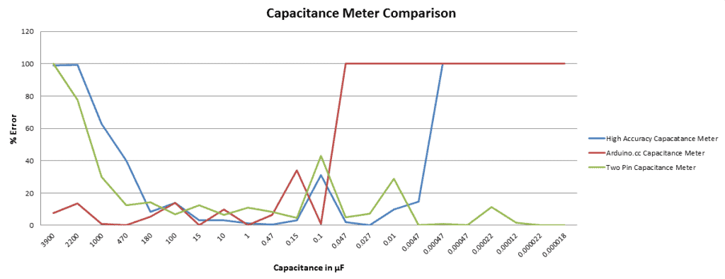
To compare the error in their measurements, I tested the output of each capacitance meter described below against capacitors of known values. This graph shows the range of values each capacitance meter is able to measure accurately:
Before we start building the circuits, let’s get a little background on how we can use the Arduino to measure capacitance…
How the Arduino Can Measure Capacitance
Each Arduino capacitance meter relies on a property of resistor capacitor (RC) circuits- the time constant. The time constant of an RC circuit is defined as the time it takes for the voltage across the capacitor to reach 63.2% of its voltage when fully charged:
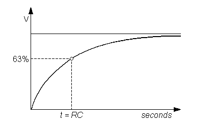
Larger capacitors take longer to charge, and therefore will create larger time constants. The capacitance in an RC circuit is related to the time constant by the equation:

Rearranging the equation to solve for capacitance gives:

Each capacitance meter has an RC circuit with known resistor values and an unknown capacitor value. The Arduino will measure the voltage at the capacitor and record the time it takes to reach 63.2% of it’s voltage when fully charged (the time constant). Since the resistance value is already known, we can use the formula above in a program that will calculate the unknown capacitance.
Capacitance Meter for 1 uF to 3900 uF Capacitors
This capacitance meter is one I found on the Arduino.cc website. After testing it, I found that it can measure values from about 0.1 μF to 3900 μF (I didn’t test it above 3900 μF) with reasonable accuracy.
The Circuit
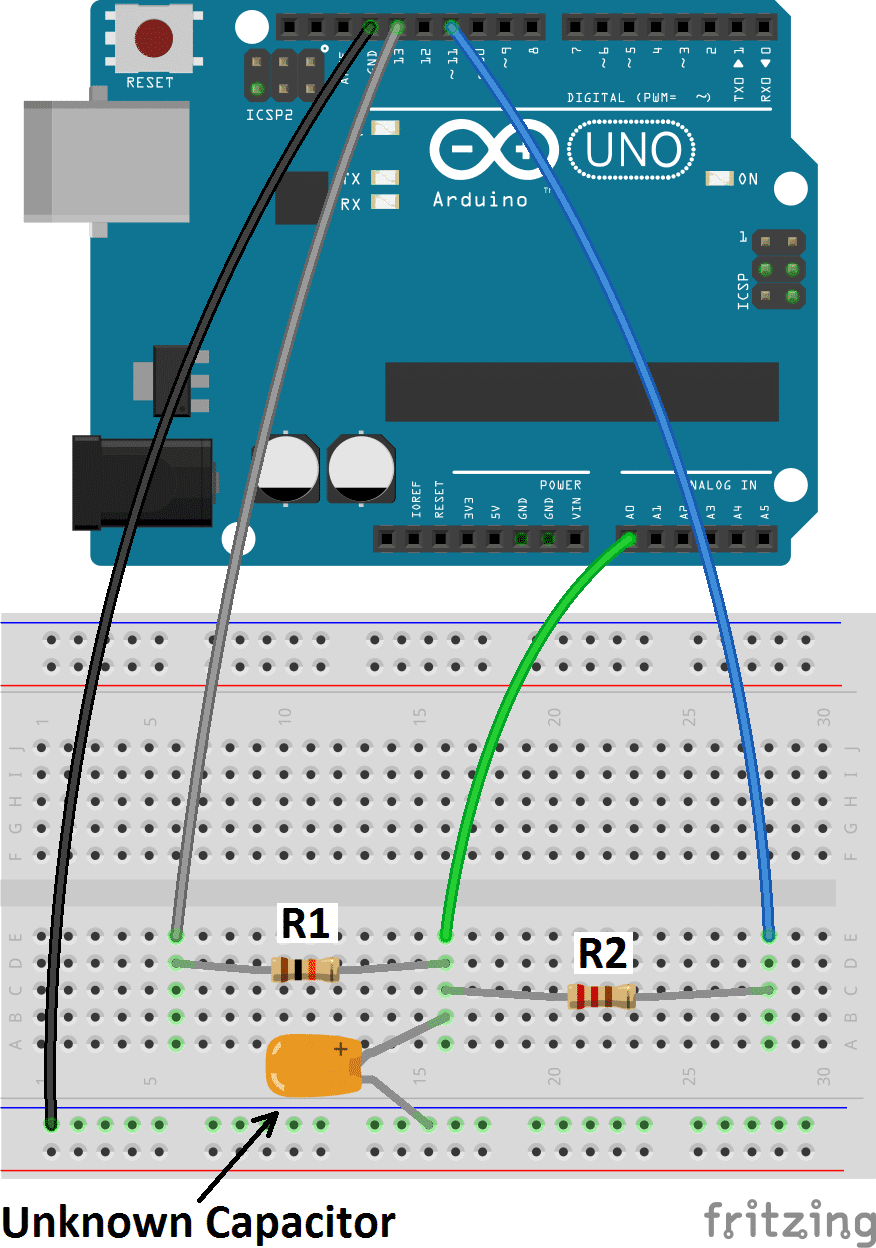
Follow this diagram to set it up:
- R1 = 10K Ohms
- R2 = 220 Ohms
The Code for Serial Monitor Output
To display the readings on the Arduino serial monitor, connect the Arduino to your PC, open the Arduino IDE and upload this code to it:
#define analogPin 0
#define chargePin 13
#define dischargePin 11
#define resistorValue 10000.0F

unsigned long startTime;
unsigned long elapsedTime;
float microFarads;
float nanoFarads;

void setup(){
  pinMode(chargePin, OUTPUT);
  digitalWrite(chargePin, LOW);
  Serial.begin(9600);
}

void loop(){
  digitalWrite(chargePin, HIGH);
  startTime = millis();
  while(analogRead(analogPin) < 648){
  }

  elapsedTime= millis() - startTime;
  microFarads = ((float)elapsedTime / resistorValue) * 1000;
  Serial.print(elapsedTime);
  Serial.print(" mS    ");

  if (microFarads > 1){
    Serial.print((long)microFarads);
    Serial.println(" microFarads");
  }

  else{
    nanoFarads = microFarads * 1000.0;
    Serial.print((long)nanoFarads);
    Serial.println(" nanoFarads");
    delay(500);
  }

  digitalWrite(chargePin, LOW);
  pinMode(dischargePin, OUTPUT);
  digitalWrite(dischargePin, LOW);
  while(analogRead(analogPin) > 0){
  }

  pinMode(dischargePin, INPUT);
}
The Code for LCD Output
To use this meter with an LCD screen, connect the LCD to your Arduino (see How to Set Up an LCD Display on an Arduino if you need instructions). Pin 11 will be used for the LCD, so wire the capacitance meter using pin 8 instead of pin 11. Here’s the code:
#define analogPin 0
#define chargePin 13
#define dischargePin 8
#define resistorValue 10000.0F
#include <LiquidCrystal.h>

LiquidCrystal lcd(12, 11, 5, 4, 3, 2);

unsigned long startTime;
unsigned long elapsedTime;
float microFarads;
float nanoFarads;

void setup(){
  pinMode(chargePin, OUTPUT);
  digitalWrite(chargePin, LOW);
  lcd.begin(16, 2);
}

void loop(){
  digitalWrite(chargePin, HIGH);
  startTime = millis();
  while(analogRead(analogPin) < 648){
  }

  elapsedTime= millis() - startTime;
  microFarads = ((float)elapsedTime / resistorValue) * 1000;
  lcd.print(elapsedTime);
  lcd.print(" mS");
  delay(2000);
  lcd.clear();
  delay(500);

  if (microFarads > 1){
    lcd.print(microFarads);
    lcd.print(" uF");
    delay(2000);
  }

  else{
    nanoFarads = microFarads * 1000.0;
    lcd.print(nanoFarads);
    lcd.print(" nF");
    delay(2000);
  }

  lcd.clear();
  digitalWrite(chargePin, LOW);
  pinMode(dischargePin, OUTPUT);
  digitalWrite(dischargePin, LOW);
  while(analogRead(analogPin) > 0){
  }

  pinMode(dischargePin, INPUT);
}
Measurement
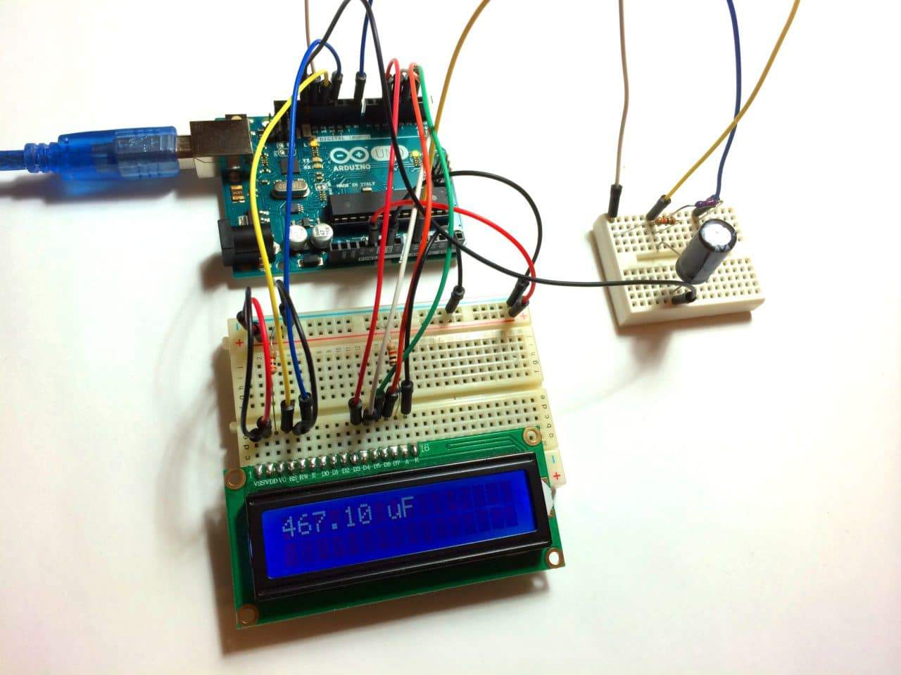
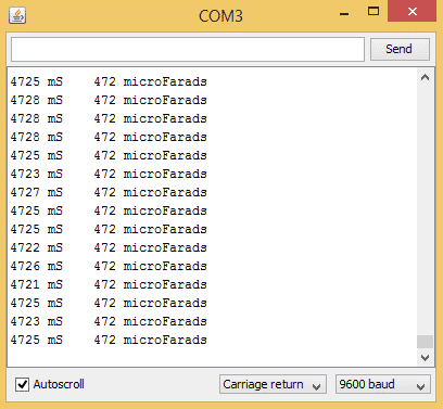
Now we’re ready to start measuring some capacitors. Insert an unknown capacitor into the breadboard as shown in the diagram above. Then open the serial monitor to see the time constant and capacitance values. These are the readings I got from a 470 μF electrolytic capacitor:
The first column shows the capacitor’s time constant, and the second column is the capacitance measurement. The units will change automatically from microFarads to nanoFarads. If you’re using an LCD to output the readings, the display will alternate between the time constant and the capacitance reading.
You’ll notice with larger capacitors that it takes longer for the Arduino to output a reading. That’s because larger capacitors have larger time constants and therefore take longer to reach 63.2% of their voltage when fully charged. For example, the 3900 μF capacitor I tested took several minutes between readings.
Capacitance Meter for 180 uF to 0.0047 uF Capacitors
This is a “high accuracy” capacitance meter developed by Nick Gammon.
The Circuit
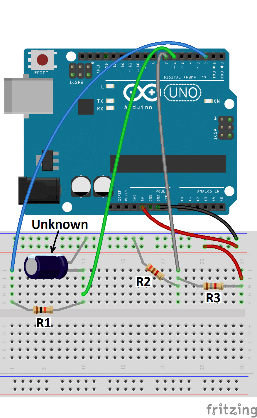
Follow the diagram below to build it:
- R1= 10K Ohm
- R2= 3.1K Ohm
- R3= 1.8K Ohm
The Code for Serial Monitor Output
To use this capacitance meter using the serial monitor for data output, connect the Arduino to your PC, open the Arduino IDE, and upload this code to the Arduino:
const byte pulsePin = 2;
const unsigned long resistance = 10000;

volatile boolean triggered;
volatile boolean active;
volatile unsigned long startTime;
volatile unsigned long duration;

ISR (ANALOG_COMP_vect){
  unsigned long now = micros ();
  if (active){
    duration = now - startTime;
    triggered = true;
    digitalWrite (pulsePin, LOW);
    }
  }

void setup (){
  pinMode(pulsePin, OUTPUT);
  digitalWrite(pulsePin, LOW);
  Serial.begin(9600);
  Serial.println("Started.");
  ADCSRB = 0;
  ACSR = _BV (ACI) | _BV (ACIE) | _BV (ACIS0) | _BV (ACIS1);
  }

void loop (){
  if (!active){
    active = true;
    triggered = false;
    digitalWrite (pulsePin, HIGH);
    startTime = micros ();
    }

  if (active && triggered){
    active = false;
    Serial.print ("Capacitance = ");
    Serial.print (duration * 1000 / resistance);
    Serial.println (" nF");
    triggered = false;
    delay (3000);
    }
}
The Code for LCD Output
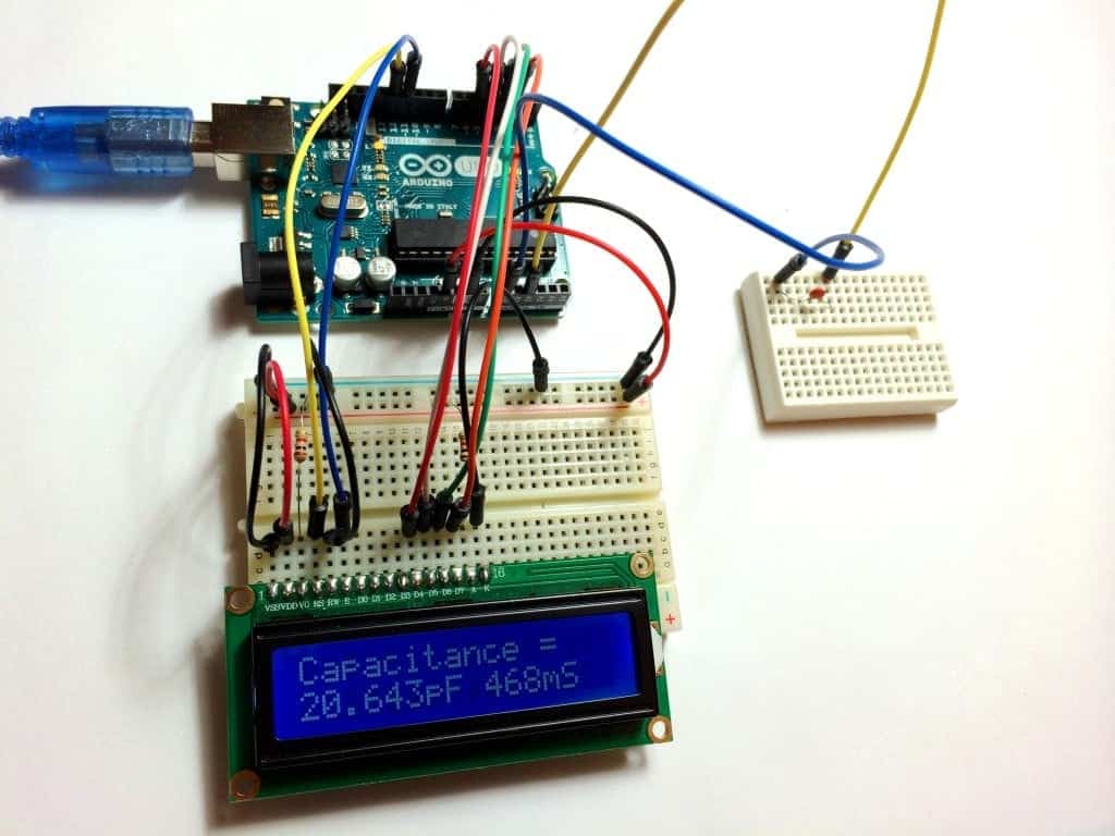
To have the capacitance measurements output to an LCD display, use the code below. Since the LCD uses pin 2, use pin 8 instead of pin 2 in the diagram above. Upload this code to the Arduino:
#include <LiquidCrystal.h>

LiquidCrystal lcd(12, 11, 5, 4, 3, 2);
const byte pulsePin = 8;
const unsigned long resistance = 10000;

volatile boolean triggered;
volatile boolean active;
volatile unsigned long startTime;
volatile unsigned long duration;

ISR (ANALOG_COMP_vect){
  unsigned long now = micros ();
  if (active){
    duration = now - startTime;
    triggered = true;
    digitalWrite (pulsePin, LOW);
    }
  }

void setup (){
  pinMode(pulsePin, OUTPUT);
  digitalWrite(pulsePin, LOW);
  lcd.begin(16, 2);
  lcd.print("Starting");
  delay(1000);
  lcd.clear();
  ADCSRB = 0;
  ACSR = _BV (ACI) | _BV (ACIE) | _BV (ACIS0) | _BV (ACIS1);
  }

void loop(){
  if (!active){
    active = true;
    triggered = false;
    digitalWrite (pulsePin, HIGH);
    startTime = micros ();
    }

  if (active && triggered){
    active = false;
    lcd.print("Capacitance = ");
    lcd.setCursor(0,1);
    lcd.print(duration * 1000 / resistance);
    lcd.print(" nF");
    triggered = false;
    delay (3000);
    lcd.clear();
    }
}
Measurement
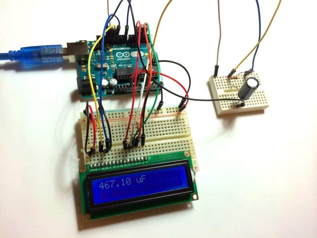
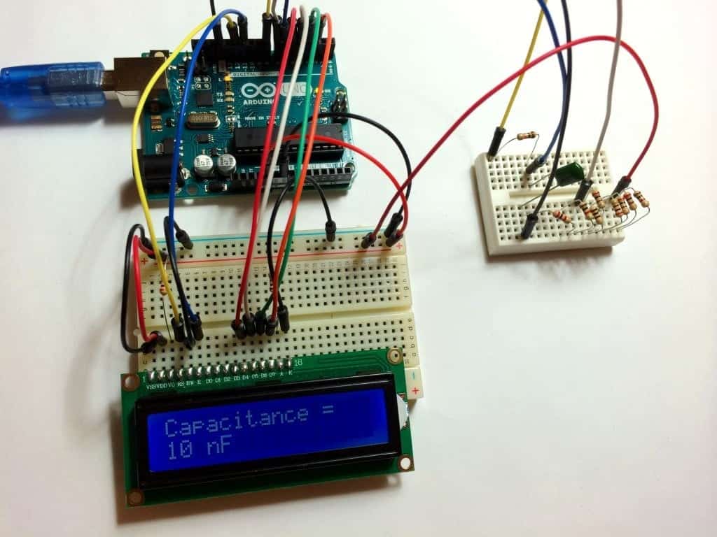
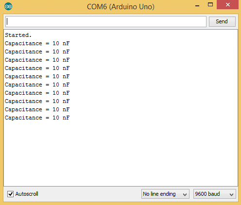
This is the reading I got from a 10 nF (0.01 μF) polyester film capacitor:
The value always reads in nF, even with capacitors in the μF range.
Capacitance Meter for 470 uF to 18 pF Capacitors
This capacitance meter had the greatest range of the three I tested. It also had the highest accuracy with smaller capacitors. It’s very easy to make too, no resistors are needed and it only uses two pins from the Arduino.
The Circuit
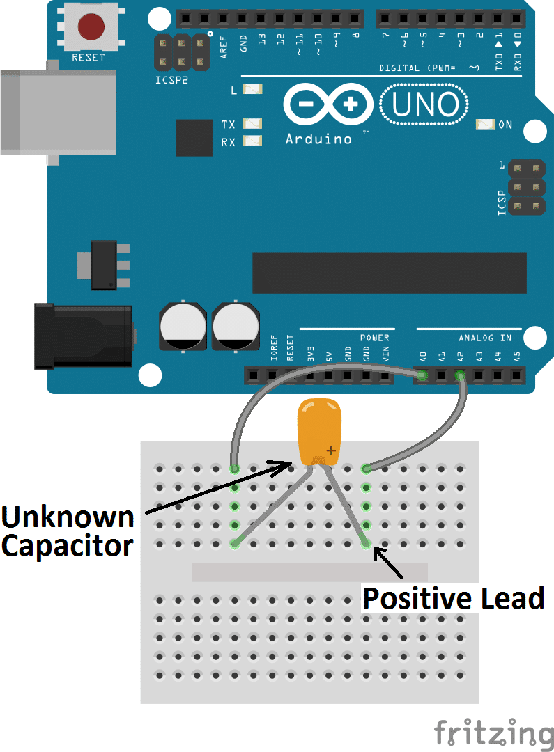
Follow this diagram to build the meter:
Note: It’s important to make sure the positive lead of the unknown capacitor is connected to pin A2 of the Arduino.
The Code for Serial Monitor Output
This code will output the capacitance readings to the Arduino’s serial monitor:
const int OUT_PIN = A2;
const int IN_PIN = A0;
const float IN_STRAY_CAP_TO_GND = 24.48;
const float IN_CAP_TO_GND  = IN_STRAY_CAP_TO_GND;
const float R_PULLUP = 34.8;
const int MAX_ADC_VALUE = 1023;

void setup(){
  pinMode(OUT_PIN, OUTPUT);
  pinMode(IN_PIN, OUTPUT);
  Serial.begin(9600);
}

void loop(){
    pinMode(IN_PIN, INPUT);
    digitalWrite(OUT_PIN, HIGH);
    int val = analogRead(IN_PIN);
    digitalWrite(OUT_PIN, LOW);

    if (val < 1000){
      pinMode(IN_PIN, OUTPUT);

      float capacitance = (float)val * IN_CAP_TO_GND / (float)(MAX_ADC_VALUE - val);

      Serial.print(F("Capacitance Value = "));
      Serial.print(capacitance, 3);
      Serial.print(F(" pF ("));
      Serial.print(val);
      Serial.println(F(") "));
    }

    else{
      pinMode(IN_PIN, OUTPUT);
      delay(1);
      pinMode(OUT_PIN, INPUT_PULLUP);
      unsigned long u1 = micros();
      unsigned long t;
      int digVal;

      do{
        digVal = digitalRead(OUT_PIN);
        unsigned long u2 = micros();
        t = u2 > u1 ? u2 - u1 : u1 - u2;
      } while ((digVal < 1) && (t < 400000L));

      pinMode(OUT_PIN, INPUT);
      val = analogRead(OUT_PIN);
      digitalWrite(IN_PIN, HIGH);
      int dischargeTime = (int)(t / 1000L) * 5;
      delay(dischargeTime);
      pinMode(OUT_PIN, OUTPUT);
      digitalWrite(OUT_PIN, LOW);
      digitalWrite(IN_PIN, LOW);

      float capacitance = -(float)t / R_PULLUP / log(1.0 - (float)val / (float)MAX_ADC_VALUE);

      Serial.print(F("Capacitance Value = "));
      if (capacitance > 1000.0){
        Serial.print(capacitance / 1000.0, 2);
        Serial.print(F(" uF"));
      }
      else{
        Serial.print(capacitance, 2);
        Serial.print(F(" nF"));
      }

      Serial.print(F(" ("));
      Serial.print(digVal == 1 ? F("Normal") : F("HighVal"));
      Serial.print(F(", t= "));
      Serial.print(t);
      Serial.print(F(" us, ADC= "));
      Serial.print(val);
      Serial.println(F(")"));
    }
    while (millis() % 1000 != 0);
}
The Code for LCD Output
To output the values to an LCD display, use this code:
#include <LiquidCrystal.h>

LiquidCrystal lcd(12, 11, 5, 4, 3, 2);
const int OUT_PIN = A2;
const int IN_PIN = A0;
const float IN_STRAY_CAP_TO_GND = 24.48;
const float IN_CAP_TO_GND = IN_STRAY_CAP_TO_GND;
const float R_PULLUP = 34.8;
const int MAX_ADC_VALUE = 1023;

void setup(){
  pinMode(OUT_PIN, OUTPUT);
  pinMode(IN_PIN, OUTPUT);
  lcd.begin(16, 2);
}

void loop(){
    pinMode(IN_PIN, INPUT);
    digitalWrite(OUT_PIN, HIGH);
    int val = analogRead(IN_PIN);
    digitalWrite(OUT_PIN, LOW);

    if (val < 1000){
      pinMode(IN_PIN, OUTPUT);

      float capacitance = (float)val * IN_CAP_TO_GND / (float)(MAX_ADC_VALUE - val);

      lcd.setCursor(0,0);
      lcd.print(F("Capacitance = "));
      lcd.setCursor(0,1);
      lcd.print(capacitance, 3);
      lcd.print(F("pF "));
      lcd.print(val);
      lcd.print("mS");
    }

    else{
      pinMode(IN_PIN, OUTPUT);
      delay(1);
      pinMode(OUT_PIN, INPUT_PULLUP);
      unsigned long u1 = micros();
      unsigned long t;
      int digVal;

      do{
        digVal = digitalRead(OUT_PIN);
        unsigned long u2 = micros();
        t = u2 > u1 ? u2 - u1 : u1 - u2;
      }

      while ((digVal < 1) && (t < 400000L));

      pinMode(OUT_PIN, INPUT);
      val = analogRead(OUT_PIN);
      digitalWrite(IN_PIN, HIGH);
      int dischargeTime = (int)(t / 1000L) * 5;
      delay(dischargeTime);
      pinMode(OUT_PIN, OUTPUT);
      digitalWrite(OUT_PIN, LOW);
      digitalWrite(IN_PIN, LOW);

      float capacitance = -(float)t / R_PULLUP / log(1.0 - (float)val / (float)MAX_ADC_VALUE);

      lcd.setCursor(0,0);
      lcd.print(F("Capacitance = "));
      if (capacitance > 1000.0){
        lcd.setCursor(0,1);
        lcd.print(capacitance / 1000.0, 2);
        lcd.print(F("uF "));
        lcd.print(val);
        lcd.print("mS");
      }

      else{
        lcd.setCursor(0,1);
        lcd.print(capacitance, 2);
        lcd.print(F("nF "));
        lcd.print(val);
        lcd.print("mS");
      }
  }
    while (millis() % 1000 != 0);
}
Measurement
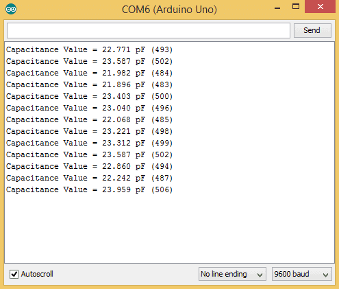
These are the readings I got from a 22 pF ceramic disc capacitor:
The units will change automatically between pF, nF and μF. The values in parentheses are the time constants for each reading (in milliseconds).
Here’s a video of this tutorial, so you can watch me set up the capacitance meters and see the Arduino measure capacitance in real time:
That’s about all there is to it! I hope you found this project as useful as I did. We also have another tutorial on building an ohm meter with the Arduino. It’s just as useful at this one, so check that out if you’re interested…
Just let me know in the comments if you have any questions or need help setting it up. Also, don’t forget to subscribe to keep updated on all of our future posts!



Why 648 in this line??: while(analogRead(analogPin) < 648){ }
648 is 63.2% of 1024… 1024 is the ADC reading for full voltage.
648 is 2/3 of 1024. 1024 being the highest value for the 10 bits ADC
I didn´t understand the two last codes in the part of the following:
1. F was not declared in this scope
2. INPUT_PULLUP was not declared in this scope
With these errors, I cannot upload the code.
Could you fix for me?
Thank you for your fast response and beforehand let me say you: thanks a lot.
Could you try updating your version of the IDE and see if that works?
how calculate equivalent series resistance (ESR) capacitor with arduino uno and simple circuit ??
See this thread on the Arduino.cc website: https://forum.arduino.cc/index.php?topic=80357.0
Thanks for posting this! I found a kludgy way to compensate for the errors in sketch 3. I did try sketch 1 to figure out what the readings were for large capacitors (I had 6800uF, 2200uF, and 1000uF capacitors on hand). So I tried to put in two calibrations, one for values less than 1500uF, and one for values greater than or equal to 1500uF (this split point was based on what I observed with the capacitors I had on hand). For values less than 1500uF, the readings produced by sketch 3 were at about 1.18 times what my Beckman Industrial DM27XL (which can only read up to 20uF) reported, so I just multiplied the capacitance value by 84.75% (which is 1 / 1.18) of what sketch 3 was producing. For values greater than or equal to 1500uF, the readings from sketch 3 were about 1.67 times greater than the readings from sketch 1, so I multiplied the capacitance value read from sketch 3 by 60% (which is 1 / 1.67). The 6800uF capacitor reading oscillated between 7051uF (which is consistent with the sketch 1 reading) and “infnf” (infinity nf?). I also created a correction variable of type float, declared at the start of the loop() function, and assigned the correction factors depending on the capacitance value read. I made the following changes to the code within the if (capacitance > 1000.0) if block starting at line 74:
if (capacitance > 1000.0)
{
lcd.setCursor(0,1);
if (capacitance < 1500000.0)
correction = 0.8475; // Multiply by correction factor 0.8475 for capacitors below 1500uF. Calibrated against Beckman Industrial DM27XL on 10uF capacitor. 7/16/15 DL
else correction = 0.60; // Multiply by correction factor 0.60 for capacitors at or above 1500uF. Calibrated against the Arduino.cc capacitance meter on 2200uF capacitor. 7/16/15 DL
lcd.print(capacitance / 1000.0 * correction, 2);
lcd.print(F("uF "));
lcd.print(val);
lcd.print("mS");
}
Obviously, using this method you could add many more split points given an accurate capacitor meter to calibrate the output from sketch 3.
I also modified the code from sketch 1 a little, so that my LCD screen would display something (rather than a blank screen) while it was figuring out the values of large capacitors. I noticed that it is best to wait for several readings from sketch 1 because it tends to "converge" on the correct value after some time (could take several minutes before you get a reading for large value capacitors). In the setup() function, I added lcd.print("Testing cap…"); right after line 17. I took out all delay() function calls; within the loop() function, after microFarads has been calculated, I cleared the screen using lcd.clear(); which removed the "Testing cap…" text; after the lines that display the elapsed time in " mS", I removed the delay(2000); function call, the lcd.clear(); and the delay(500); function calls. The next if block contains display of capacitance in microFarads and nanoFarads; I issued a call to lcd.setCursor(0, 2); so that the measured capacitance would appear on row 2 of my LCD; I removed both delay(2000); calls. Finally, I removed the lcd.clear(); function call on line 47 of sketch 1. These changes allowed me to get faster feedback that the Arduino was working, and I could see both the elapsed time (on row 1) and the capacitance value (on row 2) on my LCD.
Denny
Hi, can you share the modified project? Can it test a wide range with a single project and Math? Sorry if I misunderstood, I just want to test some capacitors from a old monitor to know what to change and I suck at electronics. I have arduinos and stuff laying around and it would cost me nothing, way cheaper to me than the capacimeter.
Hey, Thanks a million Farads! Just what I needed. I was fighting with something like the first version when the effective range I needed worked with version 3, and so simple (the hardware anyway).
hi! did the third version code part work? any corrections needed?? i am an extreme beginner and need to make my sensor work reaaaaally fast!! thanks a lot in advance. and truly a million thanks to the developers!!!!
Hi Sanhita, yes it works!
Totally awesome. I’ll have to try this capacitance meter on the caps I pull out of the monitor I’m repairing.
Hey, Thanks a lot for sharing this! In the code used for the “Two pin capacitance meter”, why did you initially set the pin mode of the “IN_PIN” as an output within the “void setup”?
what about super capacitors? 2.7V / 100 F. How to measure C?
I’m not getting exact value like 10uf capacitor shows 13uf. why?
Which circuit are you using to measure it? Also, what is the tolerance of the capacitor you’re measuring? Some capacitors can vary up to 20% of their stated value.
Regards, very interesting site, projects are very well explained thanks for the contributions and please keep adelate, wish them well and hope new tutorials
I’ve always wondered how do you measure capacitors. I’ve seen miscellaneous components testers on ebay, I even bought one, but never knew how it worked. I will try this one
hello :) !
discovered your site recently, and am eager to follow som tuts. Started with this, but duh, browsing on raspberry there is no code, and on ipad there are only some 10 lines of code, scrolling works only sideways… How do I get the full listnings? I suppose I don’t get something very obvious here :P
have since had access to the full listning via desktop machine ^^ I usually shh to raspberryPi from where I use vncserver to programm the arduino, just from with the ipad. Somehow I understand when you may not care for ther ipad :) although kind of a link to the full code wouldn’t be so wrong. Anyway, great ressource here, big thanks!
what is the value of 1st 2resestanc in circuit
resistance
Sir..I want to ask about the discharge time on the third program, the formula discharge time from where? And whats the meaning 1000L * 5 in coding. Thanks sir
sir i want ask again about proces charge and discharge capacitor for dc input in third coding..thanks sir
Do you have a commented code for the last one? Many thanks in advance
Hey, can u explain how the number 3 code works to measure capacitance? i believe it does not use the time constant method like the first two am i correct?
See file:///storage/emulated/0/wvs/c-messung.html
I made a print for a charge/discharge cycle and put some extra lines in the setup function.
Have a look at file:///storage/emulated/0/wvs/c-messung.html wher you will find the print and a commented sketch for download
A potential dumb question: can I use these circuits to measure capacitance of an air conditioner capacitor? Will it not blow my Arduino? You know, I mean the large, heavy ones rated 450VAC 50uF.(like the CBB65A-1)
the answer comes out to be double of the capacitor in last one..pls rectify it
I need to simultaneously measure capacitance and resistance using two seperate interdigitated electrode complexes.. tutorial on this will be much appreciated!!
wt is the maximum capacitance that arduino can observe
i am using Arduino observe capacitance of f300 capacitance level. is it possible
What code need to change to view its data on serial monitor instead lcd ???????
what are the variables IN_STRAY_CAP_TO_GND and IN_CAP_TO_GND used for in the last example?
hello,
please explain this line of program “t = u2 > u1 ? u2 – u1 : u1 – u2;”.
I don’t understand it!!
if u2>u1
u2-u1
else
u1-u2
T is the absolute difference of u1 and u2. T=|u1-u2|
Hello,
First of all congratulations!! Really nice job here!
I’m wondering what IN_STRAY_CAP_TO_GND, IN_CAP_TO_GND and RPULLUP means. Where does those values come from? Are they Arduino internal resistance or something like that?
Thanks!!!
Have a look at http://wordpress.codewrite.co.uk/pic/2014/01/25/capacitance-meter-mk-ii/
hey sir im using “CAPACITANCE METER FOR 470 UF TO 18 PF CAPACITORS” but i did’t under stand the arduino code …wwhat is r pullup and which resistance are you using to measure the capacitor?
Hello gobind.
The capacitance meter created utilizes two distinct methods for measuring the capacitance.
1) It measures the capacitance based on the voltage in pins A0, A2 and a known external capacitor value. (For more info about the circuit visit: http://wordpress.codewrite.co.uk/pic/2014/01/21/cap-meter-with-arduino-uno/)
2) If the capacitance is higher than a certain threshold value, let’s say 470 uF, than it measures the capacitance based on an RC circuit (this link: http://wordpress.codewrite.co.uk/pic/2014/01/25/capacitance-meter-mk-ii/). In order to avoid using an external resistor, we will utilize the RPULLUP command. Basically, when you execute the “RPULLUP” command Arduino board will use its own internal resistance (which is about 34.8 kΩ).
hi
Thank you for your post
why cap_to_gnd=24.48 ?
Sir I will discharge the capacitor by using arduino but I not understand the code for discharging.
Thank you so much this is just what I was looking for. I have a box full of caps and tough to read any of them . I am sorting them all right now.
The third method modified to use an Adafruit OLED display
/* CircuitBasicOLED.ino
Capacitance measurement per
https://www.circuitbasics.com/how-to-make-an-arduino-capacitance-meter/#
Originally from
http://wordpress.codewrite.co.uk/pic/2014/01/25/capacitance-meter-mk-ii/
Modified to use an Adafruit product 938 monochrome OLED display
*/
#include
#include
// Following two libraries needed to manage the OLED
#include
#include
#define SCREEN_WIDTH 128 // OLED display width, in pixels
#define SCREEN_HEIGHT 64 // OLED display height, in pixels
#define OLED_MOSI 2
#define OLED_CLK 3
#define OLED_DC 4
#define OLED_RESET 5
#define OLED_CS 6
Adafruit_SSD1306 display(SCREEN_WIDTH, SCREEN_HEIGHT,
OLED_MOSI, OLED_CLK, OLED_DC, OLED_RESET, OLED_CS);
const int OUT_PIN = A2;
const int IN_PIN = A0;
const float IN_STRAY_CAP_TO_GND = 24.48;
const float IN_CAP_TO_GND = IN_STRAY_CAP_TO_GND;
const float R_PULLUP = 34.8;
const int MAX_ADC_VALUE = 1023;
void setup()
{
// SSD1306_SWITCHCAPVCC = generate display voltage from 3.3V internally
if (!display.begin(SSD1306_SWITCHCAPVCC)) {
Serial.println(F(“SSD1306 allocation failed”));
for (;;); // Don’t proceed, loop forever
}
display.setTextColor(WHITE);
pinMode(OUT_PIN, OUTPUT);
pinMode(IN_PIN, OUTPUT);
}
void loop()
{
// Prepare the display to show a measurement
display.clearDisplay();
display.setCursor(0, 0); // Start at top-left corner
display.setTextSize(2); // Draw 1X-scale text
display.println(F(“CAPACITOR”));
display.setCursor(0, 18); // Position to second line
pinMode(IN_PIN, INPUT);
digitalWrite(OUT_PIN, HIGH);
int val = analogRead(IN_PIN);
digitalWrite(OUT_PIN, LOW);
if (val u1 ? u2 – u1 : u1 – u2;
}
while ((digVal < 1) && (t 1000.0) // Microfarad range
{
display.print(capacitance / 1000, 1);
display.println(F(” uF”));
}
else // Nanofarad range
{
display.print(capacitance, 1);
display.println(F(” nF”));
}
}
// Show the actual time measurement
display.setTextSize(1); // Draw 1X-scale text
display.println();
display.print(val);
display.print(” A/D “);
display.display();
delay(1);
while (millis() % 1000 != 0);
}
Excellent….I tested Version Using Only A0 and A2 pin with serial monitor and showing Good value, very useful for checking SMD capacitors value since it has no marking,.
I tested two SMD Cap 100nf and 10uF and shown near perfect value.
Many Many thanks.
Ramdas
The delay code line at the end seems odd.
It could delay for 1 second or not at all depending on the millis value returned.
I found I got more repeatable results of this is changed to a simple
delay(500);
It also makes triggering an oscilloscope a lot easier too because you get a fairly regular waveform.
Have anyone tried changing the prescaler for better accuracy (smaller time delays)?
Personally I tried messing around with it and got a bit better results (mostly with a prescaler value of 64).
Also, the timing loop on the third version put unnecessary restraints on the accuracy of the device. Micros() has a resolution of 4us, but an arduino is capable of measuring time at 62.5 ns. If you set up Timer2 to have a prescaler of 1 (no prescaler) and read directly from TCNT2 (the counter for Timer2) you can easily achieve a time resolution bellow 1 us. Also, the digitalRead is very slow, I changed it to digVal = bitRead(PINC,2) and went from 6us per loop to 2.3 us per loop. Now the loop itself is what causes most of the delay.
Hello! Have you got the modified code? Thanks in advance!
“t = u2 > u1 ? u2 – u1 : u1 – u2;”
hi i thinl u2 is always bigger than u1, nevertheless why did you use this sentence? :) plz help me
Best article on Arduino capacitance measurement that I found. If you’re interested in really fast sampling of capacitance for real time monitoring, delete the modular timing line and replace it with something like
if (currentMillis – previousMillis >= time_interval {do a timing loop}
Up to 3-4x faster.