Ultrasonic range finders are fun little sensors that can measure distance. You can use them to find the distance to an object, or to detect when something is near the sensor like a motion detector. They’re ideal for projects involving navigation, object avoidance, and home security. Because they use sound to measure distance, they work just as well in the dark as they do in the light. The ultrasonic range finder I’ll be using in this tutorial is the HC-SR04, which can measure distances from 2 cm up to 400 cm with an accuracy of ±3 mm.
In this article, I’ll show you how to make three different range finder circuits for the Arduino. The first range finder circuit is easy to set up, and has pretty good accuracy. The other two are a bit more complicated, but are more accurate because they factor in temperature and humidity. But before we get into that, lets talk about how the range finder measures distance.
Watch the video for this tutorial here:
The Speed of Sound
Ultrasonic range finders measure distance by emitting a pulse of ultrasonic sound that travels through the air until it hits an object. When that pulse of sound hits an object, it’s reflected off the object and travels back to the ultrasonic range finder. The ultrasonic range finder measures how long it takes the sound pulse to travel in its round trip journey from the sensor and back. It then sends a signal to the Arduino with information about how long it took for the sonic pulse to travel.
Knowing the time it takes the ultrasonic pulse to travel back and forth to the object, and also knowing the speed of sound, the Arduino can calculate the distance to the object. The formula relating the speed of sound, distance, and time traveled is:

Rearranging this formula, we get the formula used to calculate distance:

The time variable is the time it takes for the ultrasonic pulse to leave the sensor, bounce off the object, and return to the sensor. We actually divide this time in half since we only need to measure the distance to the object, not the distance to the object and back to the sensor. The speed variable is the speed at which sound travels through air.
The speed of sound in air changes with temperature and humidity. Therefore, in order to accurately calculate distance, we’ll need to consider the ambient temperature and humidity. The formula for the speed of sound in air with temperature and humidity accounted for is:

For example, at 20°C and 50% humidity, sound travels at a speed of:

In the equation above, it’s clear that temperature has the largest effect on the speed of sound. Humidity does have some influence, but it’s much less than the effect of temperature.
How the Ultrasonic Range Finder Measures Distance
On the front of the ultrasonic range finder are two metal cylinders. These are transducers. Transducers convert mechanical forces into electrical signals. In the ultrasonic range finder, there is a transmitting transducer and receiving transducer. The transmitting transducer converts an electrical signal into the ultrasonic pulse, and the receiving transducer converts the reflected ultrasonic pulse back into an electrical signal. If you look at the back of the range finder, you will see an IC behind the transmitting transducer labelled MAX3232. This is the IC that controls the transmitting transducer. Behind the receiving transducer is an IC labelled LM324. This is a quad Op-Amp that amplifies the signal generated by the receiving transducer into a signal that’s strong enough to transmit to the Arduino.

The HC-SR04 ultrasonic range finder has four pins:
- Vcc – supplies the power to generate the ultrasonic pulses
- GND – connected to ground
- Trig – where the Arduino sends the signal to start the ultrasonic pulse
- Echo – where the ultrasonic range finder sends the information about the duration of the trip taken by the ultrasonic pulse to the Arduino
To initiate a distance measurement, we need to send a 5V high signal to the Trig pin for at least 10 µs. When the module receives this signal, it will emit 8 pulses of ultrasonic sound at a frequency of 40 KHz from the transmitting transducer. Then it waits and listens at the receiving transducer for the reflected signal. If an object is within range, the 8 pulses will be reflected back to the sensor. When the pulse hits the receiving transducer, the Echo pin outputs a high voltage signal.
The length of this high voltage signal is equal to the total time the 8 pulses take to travel from the transmitting transducer and back to the receiving transducer. However, we only want to measure the distance to the object, and not the distance of the path the sound pulse took. Therefore, we divide that time in half to get the time variable in the d = s x t equation above. Since we already know the the speed of sound (s), we can solve the equation for distance.
Ultrasonic Range Finder Setup for Serial Monitor Output
Let’s start by making a simple ultrasonic range finder that will output distance measurements to your serial monitor. If you want to output the readings to an LCD instead, check out the next section. Connecting everything is easy, just wire it up like this:
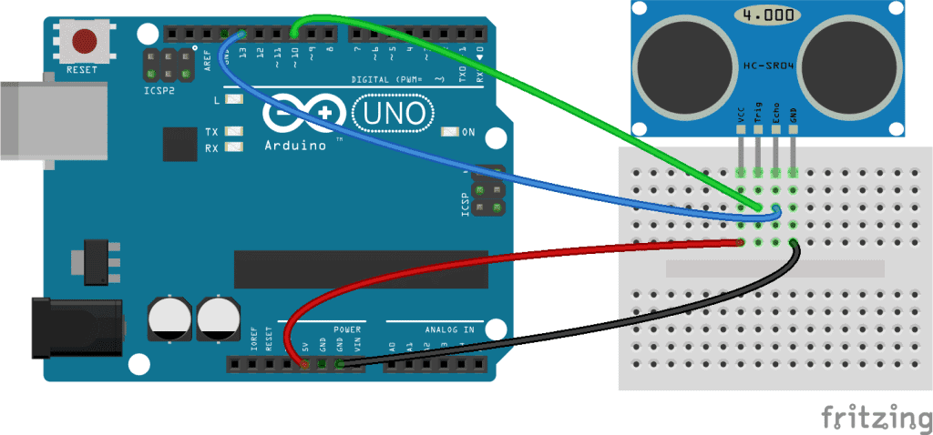
Once you have everything connected, upload this program to the Arduino:
#define trigPin 10
#define echoPin 13

void setup() {
  Serial.begin (9600);
  pinMode(trigPin, OUTPUT);
  pinMode(echoPin, INPUT);
}

void loop() {
  float duration, distance;
  digitalWrite(trigPin, LOW);
  delayMicroseconds(2);

  digitalWrite(trigPin, HIGH);
  delayMicroseconds(10);
  digitalWrite(trigPin, LOW);

  duration = pulseIn(echoPin, HIGH);
  distance = (duration / 2) * 0.0344;

  if (distance >= 400 || distance <= 2){
    Serial.print("Distance = ");
    Serial.println("Out of range");
  }
  else {
    Serial.print("Distance = ");
    Serial.print(distance);
    Serial.println(" cm");
    delay(500);
  }
  delay(500);
}
Explanation of the Code
- Line 11: Declares the variables
durationanddistance. - Lines 12 and 13: Sends a 2 µs LOW signal to the
trigPinto make sure it’s turned off at the beginning of the program loop. - Lines 15-17: Sends a 10 µs HIGH signal to the
trigPinto initiate the sequence of eight 40 KHz ultrasonic pulses sent from the transmitting transducer. - Line 19: Defines the
durationvariable as the length (in µs) of any HIGH input signal detected at theechoPin. The Echo pin output is equal to the time it takes the emitted ultrasonic pulse to travel to the object and back to the sensor. - Line 20: Defines the
distancevariable as the duration (time in d = s x t) multiplied by the speed of sound converted from meters per second to centimeters per µs (0.0344 cm/µs). - Lines 22-24: If the distance is greater than or equal to 400 cm, or less than or equal to 2 cm, display “Distance = Out of range” on the serial monitor.
- Lines 26-30: If the distance measurement is not out of range, display the distance calculated in line 20 on the serial monitor for 500 ms.
Ultrasonic Range Finder With LCD Output
If you want to output the distance measurements to a 16X2 LCD, follow this diagram to connect the range finder and LCD to your Arduino:
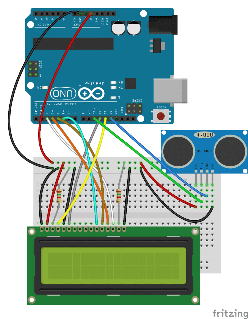
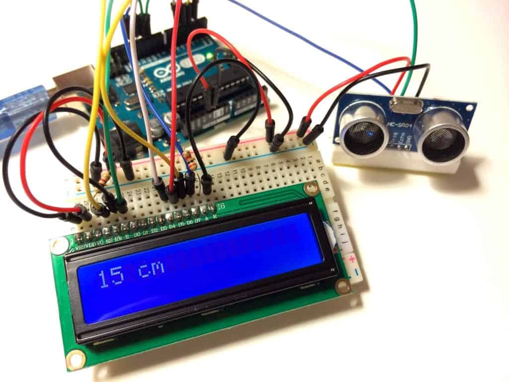
If you need more help connecting the LCD, try our other tutorial on setting up an LCD on the Arduino. When everything is connected, upload this code to the Arduino:
#include <LiquidCrystal.h>
#define trigPin 10
#define echoPin 13

LiquidCrystal lcd(12, 11, 5, 4, 3, 2);

void setup() {
  pinMode(trigPin, OUTPUT);
  pinMode(echoPin, INPUT);
}

void loop() {
  float duration, distance;
  digitalWrite(trigPin, LOW);
  delayMicroseconds(2);

  digitalWrite(trigPin, HIGH);
  delayMicroseconds(10);
  digitalWrite(trigPin, LOW);

  duration = pulseIn(echoPin, HIGH);
  distance = (duration / 2) * 0.0344;

  if (distance >= 400 || distance <= 2){
    lcd.print("Out of range");
    delay(500);
  }
  else {
    lcd.print(distance);
    lcd.print(" cm");
    delay(500);
  }
  delay(500);
  lcd.clear();
}
A Higher Accuracy Ultrasonic Range Finder
Since temperature is a variable in the speed of sound equation above (c = 331.4 + (0.606 x T) + (0.0124 x H)), the temperature of the air around the sensor affects our distance measurements. To compensate for this, all we need to do is add a thermistor to our circuit and input its readings into the equation. This should give our distance measurements greater accuracy. A thermistor is a variable resistor that changes resistance with temperature. To learn more about thermistors, check out our article, Arduino Thermistor Temperature Sensor Tutorial. Here is a diagram to help you add a thermistor to your range finder circuit:
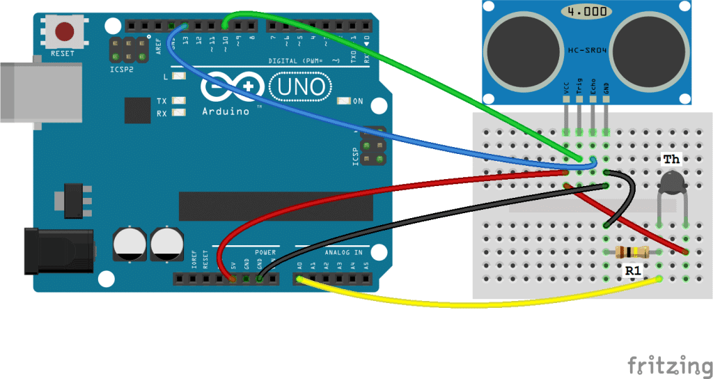
- R1 = 10K Ohm resistor
- Th = 10K Ohm thermistor
Note: the value of R1 should equal the resistance of your thermistor.
After everything is connected, upload this code to the Arduino:
#include <math.h>
#define trigPin 10
#define echoPin 13

double Thermistor(int RawADC) {
 double Temp;
 Temp = log(10000.0*((1024.0/RawADC-1)));
 Temp = 1 / (0.001129148 + (0.000234125 + (0.0000000876741 * Temp * Temp ))* Temp );
 Temp = Temp - 273.15;
 return Temp;
}

void setup() {
  Serial.begin (9600);
  pinMode(trigPin, OUTPUT);
  pinMode(echoPin, INPUT);
}

void loop() {
  int val;
  double temp;
  val=analogRead(0);
  temp=Thermistor(val);

  float duration, distance;
  float spdSnd;
  digitalWrite(trigPin, LOW);
  delayMicroseconds(2);

  digitalWrite(trigPin, HIGH);
  delayMicroseconds(10);
  digitalWrite(trigPin, LOW);

  duration = pulseIn(echoPin, HIGH);
  spdSnd = 331.4 + (0.606 * temp) + 0.62;
  distance = (duration / 2) * (spdSnd / 10000);

  if (distance >= 400 || distance <= 2){
    Serial.print("Distance = ");
    Serial.println("Out of range");
  }
  else {
    Serial.print("Distance = ");
    Serial.print(distance);
    Serial.println(" cm");
    delay(500);
  }
  delay(500);
}
Explanation of the Code
In the basic range finder program at the beginning of this article, we used the formula d = s x t to calculate the distance. In this program, we use the formula that accounts for temperature and humidity (c = 331.4 + (0.606 x T) + (0.0124 x H)).
In lines 5-10, the Steinhart-Hart equation is used to convert the thermistor resistance values to temperature, which are stored in a variable called temp. In line 35, we add a new variable (spdSnd) which contains the speed of sound equation. The output from the spdSnd variable is used as the speed in the distance function on line 36.
The Very High (Almost Too High) Accuracy Ultrasonic Range Finder
The temperature compensated ultrasonic range finder circuit is pretty accurate for what most people will use it for. However, there’s another factor affecting the speed of sound in air (and therefore the distance calculation), and that is humidity. You can tell from the speed of sound equation that humidity only has a small effect on the speed of sound, but lets check it out anyway.
There are several types of humidity sensors you can use on the Arduino, but I will be using the DHT11 humidity and temperature sensor. This module actually has a thermistor in addition to the humidity sensor, so the set up is really simple:
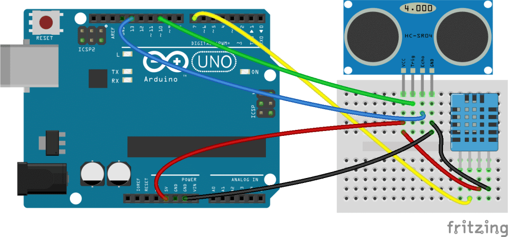
After everything is connected, we’ll need to install a special library to run the code. The library is the DHTLib library written by Rob Tillaart. The library is easy to install. First, download the .zip file below. Then in the Arduino IDE, go to Sketch>Include Library>Add ZIP Library, then select the DHTLib.zip file.
After the library is installed, upload this code to your Arduino:
#include <dht.h>

#define trigPin 10
#define echoPin 13
#define DHT11_PIN 7

dht DHT;

void setup() {
  Serial.begin (9600);
  pinMode(trigPin, OUTPUT);
  pinMode(echoPin, INPUT);
}

void loop() {

  float duration, distance;
  float speed;

  digitalWrite(trigPin, LOW);
  delayMicroseconds(2);
  digitalWrite(trigPin, HIGH);
  delayMicroseconds(10);
  digitalWrite(trigPin, LOW);

  duration = pulseIn(echoPin, HIGH);
  speed = 331.4 + (0.606 * DHT.temperature) + (0.0124 * DHT.humidity);
  distance = (duration / 2) * (speed / 10000);

  if (distance >= 400 || distance <= 2){
    Serial.print("Distance = ");
    Serial.println("Out of range");
  }
  else {
    Serial.print("Distance = ");
    Serial.print(distance);
    Serial.println(" cm");
    delay(1000);
  }
  delay(1000);
}
Explanation of the Code
The temperature and humidity readings output by the DHT11 are digital, so we don’t need to use the Steinhart-Hart equation to convert the thermistor’s resistance to temperature. The DHTLib library contains all of the functions needed to get the temperature and humidity in units we can use directly in the speed of sound equation. The variables for temperature and humidity are named DHT.temperature and DHT.humidity. Then, speed is used as a variable in the distance equation on line 28.
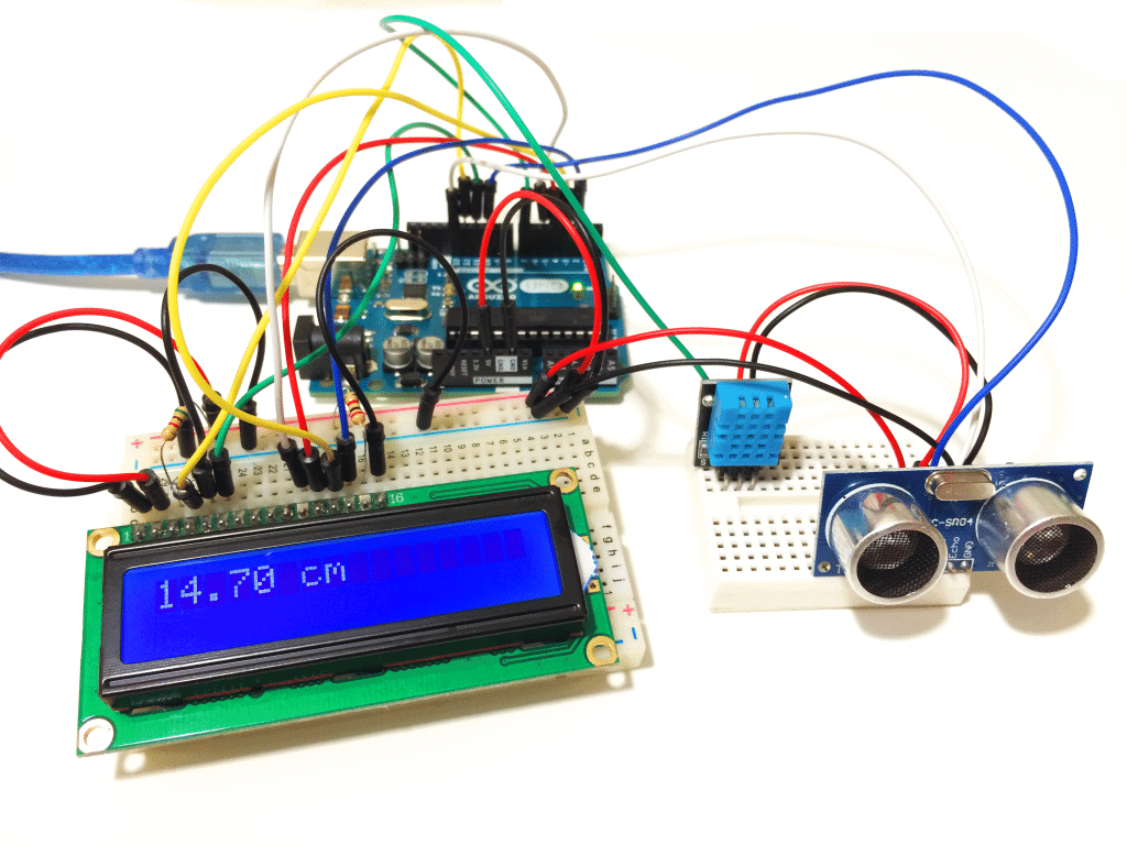
To output the distance measurements to an LCD, first connect your LCD following our tutorial How to Set Up an LCD Display on an Arduino, then upload this code:
#include <dht.h>
#include <LiquidCrystal.h>

#define trigPin 10
#define echoPin 13
#define DHT11_PIN 7

LiquidCrystal lcd(12, 11, 5, 4, 3, 2);

dht DHT;

void setup() {
  pinMode(trigPin, OUTPUT);
  pinMode(echoPin, INPUT);
}

void loop() {

  float duration, distance;
  float speed;

  digitalWrite(trigPin, LOW);
  delayMicroseconds(2);
  digitalWrite(trigPin, HIGH);
  delayMicroseconds(10);
  digitalWrite(trigPin, LOW);

  duration = pulseIn(echoPin, HIGH);
  speed = 331.4 + (0.606 * DHT.temperature) + (0.0124 * DHT.humidity);
  distance = (duration / 2) * (speed / 10000);

  if (distance >= 400 || distance <= 2){
     lcd.print("Out of range");
    delay(500);
  }
   else {
    lcd.print(distance);
    lcd.print(" cm");
    delay(500);
  }
  delay(500);
  lcd.clear();
}
Watch the video tutorial to see the ultrasonic range finder circuits in action:
Thanks for reading! Leave a comment if you have any questions about how to set these up. If you like our articles here at Circuit Basics, subscribe and we’ll let you know when we publish new articles. Also, if you know anyone else that would find this article helpful, please share it!





Great tutorial! I have the HC-SR04 wired up right now and was about to put the TMP36 in for added accuracy. I took a break to check twitter and saw one of your posts then thought to see what you had done with the HC-SR04 and found this :-)
This is very helpful, thanks for everything, it was easy to set up.
Sir i want total code for this project when using lcd .I need urgent. Pls i give you my email id
https://www.circuitbasics.com/arduino/
Hi Shankey, each circuit has code for outputting the measurements to an LCD. It’s up there in the post…
The Very High (Almost Too High) Accuracy Ultrasonic Range Finder – How is calibration done on this sketch? Thx
To calibrate, place a ruler in front of the range finder and measure the distance to a test object. If the distance output by the range finder is more than the actual distance, subtract the difference from the formula in line 28 of the code. For example, if my range finder displays 17 cm, but the actual distance is 15 cm, I would subtract 2 cm in the formula in line 28 like this: distance = ((duration / 2) * (speed / 10000)) – 2;
If the distance measured by the range finder is less than the actual distance, then you would add the difference to the formula in line 28; For example: distance = ((duration / 2) * (speed / 10000)) + 2;
Thx. I was of the grid for a while. Will try it out soon.
sir tell me the value of resistor it seem some problem or we use any resistance value
In the Higher Accuracy Ultrasonic Range Finder circuit, the value of the resistor is the same order of magnitude as the value of your thermistor. Thermistors are available in different resistances (usually 10K Ohm or 100K Ohm). So if you have a 10K Ohm thermistor, your resistor should be 10K Ohm. If you have a 100K Ohm thermistor, your resistor should be 100K Ohm. Check out our article on thermistors on the Arduino for more information.
I set up the first example and wanted to find out how good the accuracy of the messurement is and add some lines.
Works well but why the hack does it show values above and below 3?
After I eliminated these I got the following results:
avarage deviation= 0,2538
max deviation 2,28
standard deviation = 0,3949
#define trigPin 4
#define echoPin 2
void setup() {
Serial.begin (9600);
pinMode(trigPin, OUTPUT);
pinMode(echoPin, INPUT);
}
void loop() {
float duration, distance, distancealt, abweichung;
digitalWrite(trigPin, LOW);
delayMicroseconds(2);
digitalWrite(trigPin, HIGH);
delayMicroseconds(10);
digitalWrite(trigPin, LOW);
duration = pulseIn(echoPin, HIGH);
distancealt = (duration / 2) * 0.0344;
delay(500);
digitalWrite(trigPin, LOW);
delayMicroseconds(2);
digitalWrite(trigPin, HIGH);
delayMicroseconds(10);
digitalWrite(trigPin, LOW);
duration = pulseIn(echoPin, HIGH);
distance = (duration / 2) * 0.0344;
abweichung = distance – distancealt;
//Serial.print(“Distance = “);
//Serial.print(distance);
//Serial.print(” cm”);
if (abweichung = 3){
Serial.println(abweichung);
}
else {
Serial.println(“Scheiße”);
}
}
Sorry hab mich am Schluss aufgeregt ;-D Macht mich echt verrückt – warum funktioniert das nicht!
It nearly works nothing at the moment and I can’t find out why. Termperaturreadings doesn’t work either:
#include
dht DHT;
#define DHT11_PIN 7
void setup() {
Serial.begin (9600);
}
void loop() {
Serial.print(DHT.temperature);
delay(1000);
}
Error message:
Arduino: 1.6.9 (Windows 7), Board: “Arduino/Genuino Uno”
libraries\DHTLib\dht.cpp.o: In function `dht::_readSensor(unsigned char, unsigned char)’:
C:\Users\name.forename\Documents\Arduino\libraries\DHTLib/dht.cpp:106: multiple definition of `dht::_readSensor(unsigned char, unsigned char)’
sketch\dht.cpp.o:sketch/dht.cpp:106: first defined here
libraries\DHTLib\dht.cpp.o: In function `dht::_readSensor(unsigned char, unsigned char)’:
C:\Users\name.forename\Documents\Arduino\libraries\DHTLib/dht.cpp:106: multiple definition of `dht::read11(unsigned char)’
sketch\dht.cpp.o:sketch/dht.cpp:106: first defined here
libraries\DHTLib\dht.cpp.o: In function `dht::_readSensor(unsigned char, unsigned char)’:
C:\Users\name.forename\Documents\Arduino\libraries\DHTLib/dht.cpp:106: multiple definition of `dht::read(unsigned char)’
sketch\dht.cpp.o:sketch/dht.cpp:106: first defined here
collect2.exe: error: ld returned 1 exit status
exit status 1
Fehler beim Kompilieren für das Board Arduino/Genuino Uno.
Dieser Bericht wäre detaillierter, wenn die Option
“Ausführliche Ausgabe während der Kompilierung”
in Datei -> Voreinstellungen aktiviert wäre.
After several searches I finally found the solution. You need to close all arduino project open
C:\Users\name.forename\AppData\Local\Arduino15\preferences.txt
and set these to true -> afterwards everything worked :-D
build.verbose=true
upload.verbose=true
Hope that helps others!
Good night good fight ;-)))
Hi Hans, thanks for that.. Glad you got it going… By the way, which version of the DHTLib library were you using? The version in the zip file above is 0.1.14. I have heard recently that there are problems with the latest version (0.1.21).
sir what resistor did you used on the LCD? Please specify the RESISTOR
The resistors for the LCD are for the backlight brightness and screen contrast. I used 220 Ohms for both, but you might want to play around with the values to find something that you like.
The code samples only show the first 10 lines. Where can I get all the code?
Hi, on mobile the code only shows 10 lines for some reason. You need to be on a desktop to be able to scroll down. Sorry about that…
hi i wanted to insert display and then measure distance then how to do that?
why distance is showing out of range
Which range finder circuit is that happening with?
Hi Circuit Basics! Your video was great! I followed all the steps while setting up the Ultrasonic Range Finder (SR04) but as soon as I click Serial Monitor to check the distance being measured I get the same message”Out of Range”. I’ve followed your instructions on the website and the video several times and also tried different types of objects in front of the Ultrasonic Range Finder but that has not helped me. Is it possible that the Ultrasonic Range Finder doesn’t work properly? If it is so, how do I check that? Could you please help me with this? Thanks!
HC-SR04.Showing out of range.
HI, I was wondering if someone could help me with this. I am using a HY-SR05 and the distance readings are unstable. In particular, when I point the range finder at myself at a distance of about 40cm, half of the readings come out as “Out of range”. Can anyone help me?
The range finder works best when there’s a solid object for the sound pulses to bounce off of. It could be that some of the pulses are getting absorbed by your clothing and not reflecting back to the sensor. Try pointing it at a solid object and see if you get the same results… Let us know if that has any effect
hey when i compiled the very last program it is saying : Arduino: 1.6.13 Hourly Build 2016/10/21 05:33 (Windows 10), Board: “Arduino/Genuino Uno”
C:\Users\DHEERAJ SAHAJI\Desktop\sketch_oct23a\sketch_oct23a.ino:1:17: fatal error: dht.h: No such file or directory
#include
^
compilation terminated.
exit status 1
Error compiling for board Arduino/Genuino Uno.
This report would have more information with
“Show verbose output during compilation”
option enabled in File -> Preferences.
It sounds like you don’t have the DHTLib library installed. Did you install it from the link in the post? Also, you can download it from the Arduino.cc site, but the new version (0.1.21) has some issues and doesn’t seem to work. The version in the zip file above is 0.1.14, and it does work, so try that if you haven’t already. Hope that helps…
hello, what if i want have four HC_SR04 TO calculate the shortest distance of an object?? what will be the code and the circuit??
thank you & looking forward to get help
Hi can I get a lower resolution like in mm, or even lower, by changing the distance formula? If, so, could you provide this math?
Thanks for any help
Hi Jim, sure you can… Since the distance formula (distance = (duration / 2) * (speed / 10000);) is in cm, you can multiply by 10 to convert to mm. That would make it:
distance = (duration / 2) * (speed / 10000) * 10;
You’ll probably also want to change lcd.print(” cm”); to lcd.print(” mm”);
hey circuit basics thank you for your help
i got ‘o’ grade highest in my class thank you very much
That’s great Dheeraj, keep up the good work!
Hey, great project. I got a TMP36 in my Arduio kit. Anyone know how to implement this instead of the thermistor mentioned. (The TMP36 had 3 pins and returns a voltage reading. )
Hi, I would like to know if it is possible to display information from two or more sensors on the same LCD? For example, two ultrasonic sensors pointed to two different directions.
Hey could you recommend a way for me to have an LED switch on at a certain distance?
You could use an “if” statement at the end of the loop function for that… For example,
if(distance > 10) {
digitalWrite(6, HIGH);
}
else {
digitalWrite(6, LOW);
}
This would send a high signal to pin 6 when the distance is greater than 10 cm, and switch it low when the distance is less than 10 cm.
What is the power of the Ohm resistor used in the ultrasonic distance finder with lcd display 16*2?(Without temperature and humidity sensors)
Hi… Thanks very much it helps a lot! In special the calibration part
I am a first timer at this. uploaded the program and I am getting an error.
redefinition of ‘void setup()’
uploaded the ultrasonic program. I am getting an error. redefinition of ‘ void setup() ‘
okay got the redefinition of void setup figured out. now have expected ‘ } ‘ at end of input
the program looks like the one in the example?
Hi,in your code you forget to read from your DHT11. The Speed will always be 331.4 as you add 0 to it.
Must include :
int chk = DHT.read11(DHT11_PIN);
after float declarations
then you will have a measurement that takes in count 2 parameters, and adapt the speed of sound,
Greets from Hungary
okay got the redefinition of void setup figured out. now have expected ‘ } ‘ at end of input
the program looks like the one in the example?What is the power of the Ohm resistor used in the ultrasonic distance finder with lcd display 16*2?(Without temperature and humidity sensors)
This is one of the easiest tutorials to follow along with. Great Job! I’m set up with the distance and temp/humidity sensor to my Uno, but my LCD has the I2C converter on it. Any chance you or somebody could help me out with getting to distance displayed on my I2C LCD display? I know how to connect my display to the Uno, just not sure if anything needs to be changed in the sketch to work with my display properly. I hope that all makes sense.
can i get the thesis on this project??
Hey can you send a circuit diagram with dht11, lcd and ultrasonic sensor with breadboard . . .
Great primer and it runs perfectly for me.
My question is where it says the following:
speed = 331.4 + (0.606 * DHT.temperature) + (0.0124 * DHT.humidity);
Where does the 0.0124 come from? I can’t find a primary source anywhere and would love to understand the formula better.
Hi there!
I’ve been using the variation of your code with the thermostat and it’s been working perfectly. However, for a project of mine I am needing to hook up multiple Ultrasonic sensors to one Arduino board, could you please help me with the scaling this code to be able to have multiple sensors running from the single board?
Thank you!
Hello Sir,
Thank you for the knowledge you shared above, I am working on the same kind of project, I have used android to display the measures sensor will catch.
So my question is can I give audio to my android so it could read all the readings, can I give voice to android using Arduino Uno.
I used Arduino Uno, Ultrasonic Sensor, Bread Board, and Connecting Wires, What in addition we need, to give voice to readings.
Dear circuit basics,
I‘m looking for an option to install 4 of those sensors for a big platform lifted by 4 hydraulic cylinders,
Is there an option to install 4 LCD and 4 Sensors on one controller board?
1cm accuracy is enough for my project,
In future it might be of interest to use the signal of the four sensors to control four solenoidvalves.
Could you suggest something?
Thanks
BR
Markus
Hi, concerning the LCD, you will have to use IC2 bus.
For the sensor it´s simple to do 4 times the same.
As I don’t write tutorials myself, here a link.
https://www.theengineeringprojects.com/2015/02/interfacing-multiple-ultrasonic-sensor-arduino.html
Hope this is helpful, best regards
Jozsef
Dear Jozsef,
Thanks for your efforts.
I will try to solve it.
Hello, can you tell me from where I can buy or find this circuit build on this diagram?
Arduino: 1.8.9 (Windows Store 1.8.21.0) (Windows 10), Board: “Arduino/Genuino Uno”
sketch_oct31a:51:5: error: redefinition of ‘dht DHT’
dht DHT;
^
C:\Users\jayav\Desktop\sketch_oct31a\sketch_oct31a.ino:7:5: note: ‘dht DHT’ previously declared here
dht DHT;
^
C:\Users\jayav\Desktop\sketch_oct31a\sketch_oct31a.ino: In function ‘void setup()’:
sketch_oct31a:53:6: error: redefinition of ‘void setup()’
void setup() {
^
C:\Users\jayav\Desktop\sketch_oct31a\sketch_oct31a.ino:9:6: note: ‘void setup()’ previously defined here
void setup() {
^
C:\Users\jayav\Desktop\sketch_oct31a\sketch_oct31a.ino: In function ‘void loop()’:
sketch_oct31a:58:6: error: redefinition of ‘void loop()’
void loop() {
^
C:\Users\jayav\Desktop\sketch_oct31a\sketch_oct31a.ino:15:6: note: ‘void loop()’ previously defined here
void loop() {
^
exit status 1
redefinition of ‘dht DHT’
This report would have more information with
“Show verbose output during compilation”
option enabled in File -> Preferences.
Hi, i see u use 2 pin thermistor but i have a 3 pin one how to connect the cable with 3 pin thermistor ? can u show me please ?
Hello what is the max range which can be achieved by this
Could not access the Lasser range finder circuits. Confirm it’s available for those interested to construct
when ultrasonic sensor detects the obstacles then i want to print the message as “Obstacle is detected ” and when there is no obstacle then i wan to print “No obstacle found”.
To print these messages on LCD what changes i need to make.
Can you please send me code for that.
Will this method work to measure water in a plastic tank… mounting it on top, drilling the appropriate holes in the tank cap for the sensors to shoot through and looking down at the water level. Since the water moves while filling… I’m guessing that a detecting when it first hits 6″ from the top, would be all that is needed to tell the fill valve to stop adding water. Is this a good use of these components… reliable? Thanks in advance!
Mine just says out of range for the first one. It would be helpful if you added one with an lcd screen that uses an I2C backpack. Please let me know if you need the images.
quiero hacer con display de 7 segmentos 4 digitos tienen codigo desde ya gracias
You should have included a source for the equation. I don’t think the humidity term is a validated addition.