The DS18B20 temperature sensor is perfect for projects like weather stations and home automation systems. Few sensors are this easy to set up on the Raspberry Pi. They’re the same size as a transistor and use only one wire for the data signal. They’re also extremely accurate and take measurements quickly. The only other component you need is a 4.7K Ohm or 10K Ohm resistor.
In this tutorial, I’ll show you how to connect the DS18B20 to your Raspberry Pi and display the temperature readings on the SSH terminal or an LCD display.
Parts used in this tutorial:
Digital Temperature Sensors vs. Analog Temperature Sensors
Digital temperature sensors like the DS18B20 differ from analog thermistors in several important ways. In thermistors, changes in temperature cause changes in the resistance of a ceramic or polymer semiconducting material. Usually, the thermistor is set up in a voltage divider, and the voltage is measured between the thermistor and a known resistor. The voltage measurement is converted to resistance and then converted to a temperature value by the microcontroller.
Digital temperature sensors are typically silicon based integrated circuits. Most contain the temperature sensor, an analog to digital converter (ADC), memory to temporarily store the temperature readings, and an interface that allows communication between the sensor and a microcontroller. Unlike analog temperature sensors, calculations are performed by the sensor, and the output is an actual temperature value.
About the DS18B20
The DS18B20 communicates with the “One-Wire” communication protocol, a proprietary serial communication protocol that uses only one wire to transmit the temperature readings to the microcontroller.
The DS18B20 can be operated in what is known as parasite power mode. Normally the DS18B20 needs three wires for operation: the Vcc, ground, and data wires. In parasite mode, only the ground and data lines are used, and power is supplied through the data line.
The DS18B20 also has an alarm function that can be configured to output a signal when the temperature crosses a high or low threshold that’s set by the user.
A 64 bit ROM stores the device’s unique serial code. This 64 bit address allows a microcontroller to receive temperature data from a virtually unlimited number of sensors at the same pin. The address tells the microcontroller which sensor a particular temperature value is coming from.
Technical Specifications
- -55°C to 125°C range
- 3.0V to 5.0V operating voltage
- 750 ms sampling
- 0.5°C (9 bit); 0.25°C (10 bit); 0.125°C (11 bit); 0.0625°C (12 bit) resolution
- 64 bit unique address
- One-Wire communication protocol
For more details on timing, configuring parasite power, and setting the alarm, see the datasheet:
You can also watch the video version of this tutorial here:
Connect the DS18B20 to the Raspberry Pi
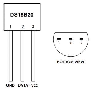
The DS18B20 has three separate pins for ground, data, and Vcc:
Wiring for SSH Terminal Output
Follow this wiring diagram to output the temperature to an SSH terminal:
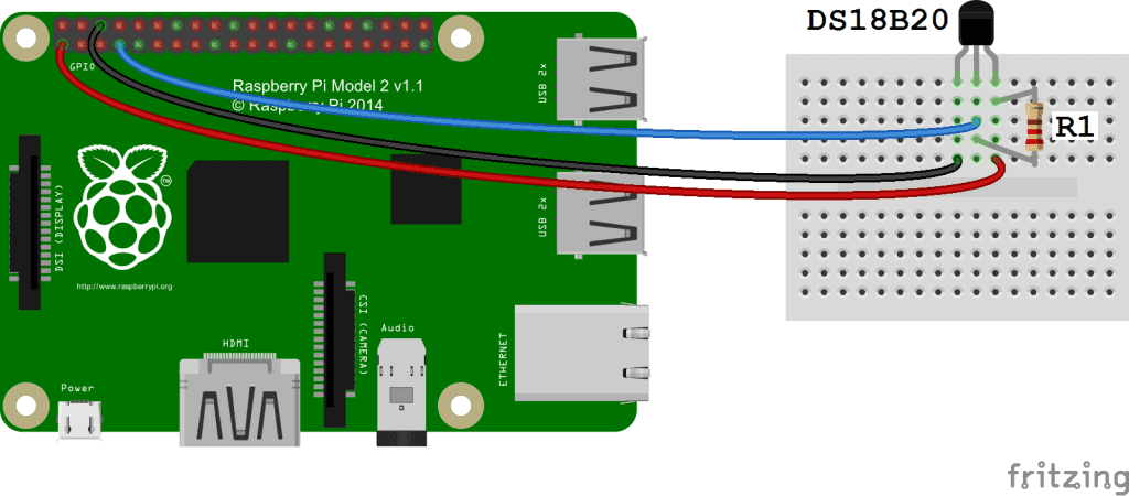
R1: 4.7K Ohm or 10K Ohm resistor
Wiring for LCD Output
Follow this diagram to output the temperature readings to an LCD:
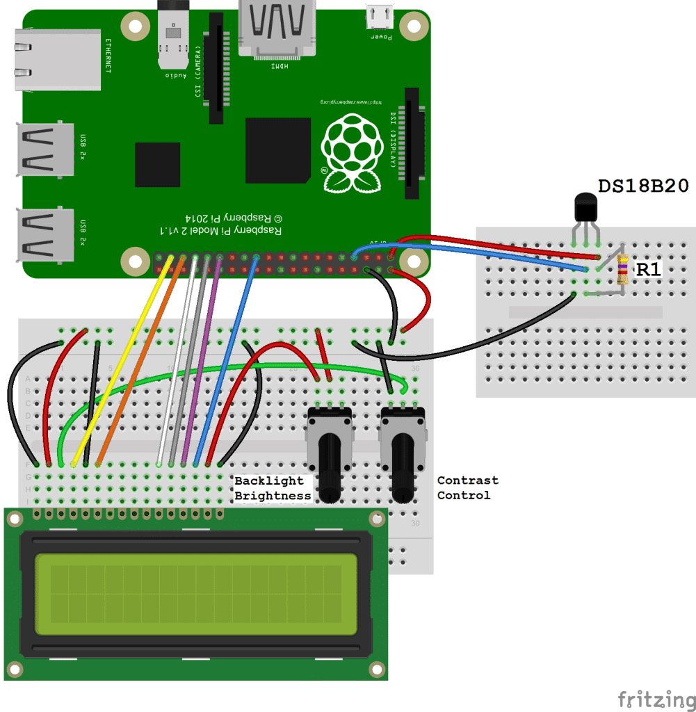
R1: 4.7K Ohm or 10K Ohm resistor
For more information about using an LCD on the Raspberry Pi, check out our tutorial Raspberry Pi LCD Set Up and Programming in Python.
Enable the One-Wire Interface
We’ll need to enable the One-Wire interface before the Pi can receive data from the sensor. Once you’ve connected the DS18B20, power up your Pi and log in, then follow these steps to enable the One-Wire interface:
1. At the command prompt, enter sudo nano /boot/config.txt, then add this to the bottom of the file:
dtoverlay=w1-gpio
2. Exit Nano, and reboot the Pi with sudo reboot
3. Log in to the Pi again, and at the command prompt enter sudo modprobe w1-gpio
4. Then enter sudo modprobe w1-therm
5. Change directories to the /sys/bus/w1/devices directory by entering cd /sys/bus/w1/devices
6. Now enter ls to list the devices:
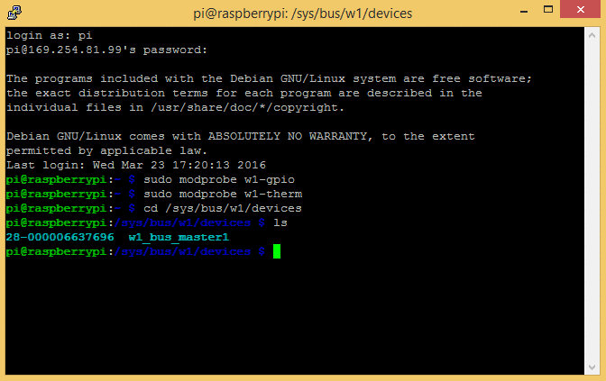
In my case, 28-000006637696 w1_bus_master1 is displayed.
7. Now enter cd 28-XXXXXXXXXXXX (change the X’s to your own address)
For example, in my case I would enter cd 28-000006637696
8. Enter cat w1_slave which will show the raw temperature reading output by the sensor:
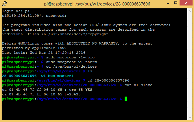
Here the temperature reading is t=28625, which means a temperature of 28.625 degrees Celsius.
9. Enter cd to return to the root directory
That’s all that’s required to set up the one wire interface. Now you can run one of the programs below to output the temperature to an SSH terminal or to an LCD…
Programming the Temperature Sensor
The examples below are written in Python. If this is your first time running a Python program, check out our tutorial How to Write and Run a Python Program on the Raspberry Pi to see how to save and run Python files.
Temperature Output to SSH Terminal
This is a basic Python program that will output the temperature readings in Fahrenheit and Celsius to your SSH terminal:
import os
import glob
import time

os.system('modprobe w1-gpio')
os.system('modprobe w1-therm')

base_dir = '/sys/bus/w1/devices/'
device_folder = glob.glob(base_dir + '28*')[0]
device_file = device_folder + '/w1_slave'

def read_temp_raw():
    f = open(device_file, 'r')
    lines = f.readlines()
    f.close()
    return lines

def read_temp():
    lines = read_temp_raw()
    while lines[0].strip()[-3:] != 'YES':
        time.sleep(0.2)
        lines = read_temp_raw()
    equals_pos = lines[1].find('t=')
    if equals_pos != -1:
        temp_string = lines[1][equals_pos+2:]
        temp_c = float(temp_string) / 1000.0
        temp_f = temp_c * 9.0 / 5.0 + 32.0
        return temp_c, temp_f

while True:
	print(read_temp())
	time.sleep(1)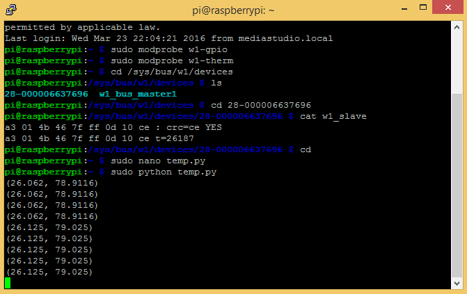
Temperature Output to an LCD
We’ll be using a Python library called RPLCD to drive the LCD. The RPLCD library can be installed from the Python Package Index, or PIP. PIP might already be installed on your Pi, but if not, enter this at the command prompt to install it:
sudo apt-get install python-pip
After you get PIP installed, install the RPLCD library by entering:
sudo pip install RPLCD
Once you have the library installed, you can run this program to output the temperature to an LCD display:
import os
import glob
import time
from RPLCD import CharLCD

lcd = CharLCD(cols=16, rows=2, pin_rs=37, pin_e=35, pins_data=[33, 31, 29, 23])

os.system('modprobe w1-gpio')
os.system('modprobe w1-therm')

base_dir = '/sys/bus/w1/devices/'
device_folder = glob.glob(base_dir + '28*')[0]
device_file = device_folder + '/w1_slave'

def read_temp_raw():
    f = open(device_file, 'r')
    lines = f.readlines()
    f.close()
    return lines

#CELSIUS CALCULATION
def read_temp_c():
    lines = read_temp_raw()
    while lines[0].strip()[-3:] != 'YES':
        time.sleep(0.2)
        lines = read_temp_raw()
    equals_pos = lines[1].find('t=')
    if equals_pos != -1:
        temp_string = lines[1][equals_pos+2:]
        temp_c = int(temp_string) / 1000.0 # TEMP_STRING IS THE SENSOR OUTPUT, MAKE SURE IT'S AN INTEGER TO DO THE MATH
        temp_c = str(round(temp_c, 1)) # ROUND THE RESULT TO 1 PLACE AFTER THE DECIMAL, THEN CONVERT IT TO A STRING
        return temp_c

#FAHRENHEIT CALCULATION
def read_temp_f():
    lines = read_temp_raw()
    while lines[0].strip()[-3:] != 'YES':
        time.sleep(0.2)
        lines = read_temp_raw()
    equals_pos = lines[1].find('t=')
    if equals_pos != -1:
        temp_string = lines[1][equals_pos+2:]
        temp_f = (int(temp_string) / 1000.0) * 9.0 / 5.0 + 32.0 # TEMP_STRING IS THE SENSOR OUTPUT, MAKE SURE IT'S AN INTEGER TO DO THE MATH
        temp_f = str(round(temp_f, 1)) # ROUND THE RESULT TO 1 PLACE AFTER THE DECIMAL, THEN CONVERT IT TO A STRING
        return temp_f

while True:

    lcd.cursor_pos = (0, 0)
    lcd.write_string("Temp: " + read_temp_c() + unichr(223) + "C")
    lcd.cursor_pos = (1, 0)
    lcd.write_string("Temp: " + read_temp_f() + unichr(223) + "F")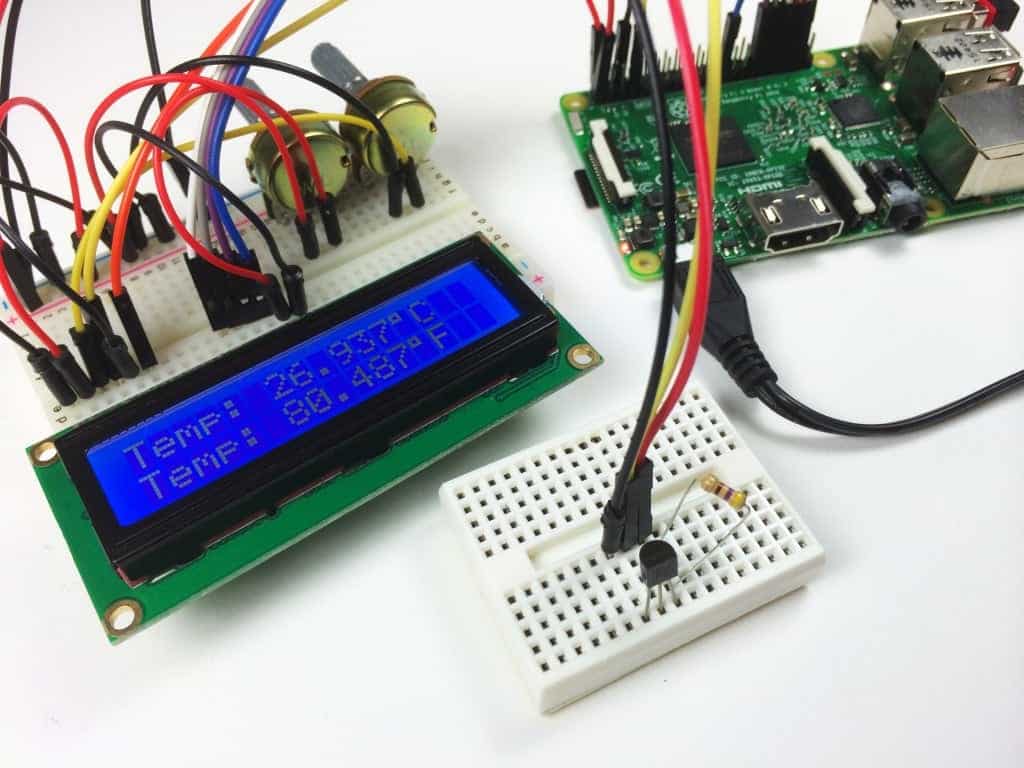
That should just about wrap it up! Hope you found it useful. Be sure to subscribe if you’d like to get an email each time we publish a new tutorial. Feel free to share it if you know someone else that would like it… And as always, let us know in the comments if you have any problems setting it up!



Hi there!
How can I do this with three sensors? Three DS18b20 and print it on the lcd?
My first attempt at using more than 1 sensor.
import os
import glob
import time
# os.system(‘modprobe w1-gpio’)
# os.system(‘modprobe w1-therm’)
base_dir = ‘/sys/bus/w1/devices/’
device_folder1 = glob.glob(base_dir + ’28*’)[0]
device_folder2 = glob.glob(base_dir + ’28*’)[1]
device_file1 = device_folder1 + ‘/w1_slave’
device_file2 = device_folder2 + ‘/w1_slave’
def read_temp_raw():
f1 = open(device_file1, ‘r’)
f2 = open(device_file2, ‘r’)
lines1 = f1.readlines()
f1.close()
lines2 = f2.readlines()
f2.close()
return (lines1, lines2)
def calculate_temp(raw):
“””Accepts raw output of DS18b20 sensor and returns a tuple of temp in C and F.
“””
equals_pos = raw[1].find(‘t=’)
if equals_pos != -1:
temp_string = raw[1][equals_pos+2:]
temp_c = float(temp_string) / 1000.0
temp_f = temp_c * 9.0 / 5.0 + 32.0
return (temp_c, temp_f)
def read_temp():
“””
“””
# wait for a valid result
lines1, lines2 = read_temp_raw()
while lines1[0].strip()[-3:] != ‘YES’:
time.sleep(0.2)
lines1, lines2 = read_temp_raw()
temp1 = calculate_temp(lines1)
temp2 = calculate_temp(lines2)
return (temp1, temp2)
while True:
print(read_temp())
time.sleep(1)
Apologies, the editor wiped out my whitespace above. I hope there is enough information for you to fix it.
…
temp1 = calculate_temp(lines1)
temp2 = calculate_temp(lines2)
return (temp1, temp2)
Is that inside the function? The indents aren’t clear.
i have the same problem, did you find a solution back then? or do you remember the generall idea?
Can i use Sensor DHT22 for this instead of DS18B20
Hi Jassim, the DHT22 will be a different set up than the DS18B20. Take a look at this tutorial on the DHT22: http://www.rototron.info/dht22-tutorial-for-raspberry-pi/
will this work with Pi 3 B+?
works great
Would you give me comments for the programs for understanding it more please? :)
My e-mail adress: t.peter222@gmail.com
How can I get only single read of temperature when I run my temp.py
I tried this several times and other web sites, other programs, all I get from the temperature sensor is 85 all the time , nothing else.
my project is to make a heating jacket and we’re using the sensors to sense when a person is cold. I dont need an led screen do you have a tutorial for that?
Sure, I would try using the SSH terminal code above, but instead of using print(read_temp()) in the while loop, use the read_temp() variable in your functions that control the heating elements in the jacket
Hey…its a non-technical question…but how do you get those wiring snapshot…Which software do you use??
Fritzing – it can be found at fritzing.org.
What is the white colored board where the Temperature Sensor is fitted called? Can this project be done without using it, i.e by fitting the Temperature Sensor into the breadboard itself?
It’s called breadboard. You can buy it really anywhere and they’re really cheap :)
what the mean of A3 01 4B 46 7F FF 0D 10 CE ?
is it a type of data ? if that a data, can i convert to string ?
It’s the serial number of the 18B20 sensor, plus a CRC number (CE in this case). Think of it as an equivalent of a MAC address for net devices. You use it as it is, in HEX format. Maybe you can store it in a DB along with the measurements.
Hi,
I have received message “modprobe: FATAL: Module w1–gpio not found” Please could you give me information what is wrong? I went step by step according to tutorial.
Thank you very much
If you are ssh in, make sure Remote GPIO is enabled in your Raspberry Pi settings. If not you will get this error.
I follow this great article for my Temperature Sensor (DS18B20) Installation, I used it in my Raspberry Pi control Room Temprature with Heater and Fan which combine a bunch of different sensor, smart devices to work together including Raspberry Pi, Smart Plug, Temperature Sensor, IR Receiver and IR LED. https://github.com/polease/HomeAutomation
Getting this error code when i try to execute the script to write output to an LCD:
Traceback (most recent call last):
File “temp.py”, line 6, in
lcd = CharLCD(cols=16, rows=2, pin_rs=37, pin_e=35, pins_data=[33, 31, 29, 23])
File “/usr/local/lib/python2.7/dist-packages/RPLCD/_init__.py”, line 14, in __init_
super(CharLCD, self).__init__(*args, **kwargs)
File “/usr/local/lib/python2.7/dist-packages/RPLCD/gpio.py”, line 95, in _init_
‘must be either GPIO.BOARD or GPIO.BCM’ % numbering_mode)
ValueError: Invalid GPIO numbering mode: numbering_mode=None, must be either GPIO.BOARD or GPIO.BCM
i also got that error, do you have any solutiion?
Had the same error, I got mine to work using an older version of RPLCD. Type in:”sudo pip install RPLCD==0.9″ instead of “sudo pip install RPLCD”
Thanks Atom,
Much appreciated.
Have you managed to get it working with the new library?
But thanks again.
#You have to add a line near the top of the program that states:
# for GPIO numbering, choose BCM
GPIO.setmode(GPIO.BCM)
# or, for pin numbering, choose BOARD
GPIO.setmode(GPIO.BOARD)
#Make sure you choose the one that matches which pin #s you are using!
I followed surely all the steps correctly including the wiring but when i run the programm the temperature is printed correctly at the command window of raspberry but the screen is just lighted blank
Hello.
I’m building a server room for my mining machinery. Since I have a bunch of multirotor equipment on stock i would like to build an air circulating system where i want to use brushless motors with props to suck out hot air from the room.. with your build here: https://www.youtube.com/watch?v=aEnS0-Jy2vE the system is almost finished except the wiring up to several motors with speedcontrollers (esc). Can you help me out on this one??
Would love to pay you for your work.
In case please email me at: wo@absnet.no or call me on +47 48 49 50 51
Thanks in advance.
So many fantastic videos you have made, easy to understand your pedagogic sense :)
-walther-
hello!
i have followed all the steps but in the it says w1_slave is not found
pi@raspberrypi:~ $ sudo modprobe w1-gpio
pi@raspberrypi:~ $ sudo modprobe w1-therm
pi@raspberrypi:~ $ cd /sys/bus/w1/devices
pi@raspberrypi:/sys/bus/w1/devices $ ls
00-800000000000 w1_bus_master1
pi@raspberrypi:/sys/bus/w1/devices $ cd 00-800000000000
pi@raspberrypi:/sys/bus/w1/devices/00-800000000000 $ cat w1_slave
cat: w1_slave: No such file or directory
can you please tell what can be the problem?
thank you
Anything that starts with 00-XXXXXXXXXXX is a phantom reading. Faulty sensor will cause this. Google tells me that it is not that uncommon for them to be bad.
I also got this when I tried plugging the sensor without a resistor.
00-080000000000 is not your temp sensor!
Temp sensor starts with 28-XXXXXXXXXXX!
Check your wiring or you may have a faulty sensor!
how do i get the displays to reflect on my android. supposing im building a software that will display the temperature of my heated material.
in using raspberry pi and the temperature sensor, following the above commands, instead of displaying it on the LCD, how do i get it to be displayed on the software installed on the android device.
Thanks
please how do i get the temperature readings to display on my android. lets say if iv created a software purposely to display the readings.. What connection do i need to make?
Why do you have the first time.sleep in the def?
I deleted it and still worked
Is the f.close really needed?
Everytime i exeute output to LCD i get this error
Traceback (most recent call last):
File “temp_lcd.py”, line 6, in
lcd=CharLCD(cols=16, rows=2, pin_rs=37, pin_e=35, pins_data=[33, 31, 29, 23])
TypeError: this constructor takes no arguments
is the problem in CharLCD?
Works great! Many thanks.
Is it Possible to use both LCD and LED in single python file ?
I’m Setting the GPIO for LED using
GPIO.setmode(GPIO.BCM)
GPIO.setup(18,GPIO.OUT)
When I add
lcd = CharLCD(cols=16, rows=2, pin_rs=37, pin_e=35, pins_data=[33, 31, 29, 23])
says not GPIO configured
lcd = CharLCD(cols=16, rows=2, pin_rs=37, pin_e=35, pins_data=[33, 31, 29, 23], numbering_mode=GPIO.BCM)
GPIO has already configured.
how to use both LED GPIO and want to use LCD. can any one help
can you give me code to combine temperature and matrix keypad input?
Hello, I have been given the bright idea to make a temperature sensor to put in one of our server rooms. This setup looks like what I’m going for, a couple of questions though.
Is there anyway we could set a temp that we don’t want exceeded, and if when it does get exceeded can we get an email alert or text alert?
Secondly, how could we clean this up? Make it look neat and clean. Maybe a box or something. Just need some ideas.
Thanks
Hi i m newbe. i am getting errors at the last while. i dont know the end of while statement. please check program and send me correction on my email.
import os
import glob
import time
from RPLCD import CharLCD
lcd = CharLCD(cols=16, rows=2, pin_rs=37, pin_e=35, pins_data=[33, 31, 29, 23])
os.system(‘modprobe w1-gpio’)
os.system(‘modprobe w1-therm’)
base_dir = ‘/sys/bus/w1/devices/’
device_folder = glob.glob(base_dir + ’28*’)[0]
device_file = device_folder + ‘/w1_slave’
def read_temp_raw():
f = open(device_file, ‘r’)
lines = f.readlines()
f.close()
return lines
#CELSIUS CALCULATION
def read_temp_c():
lines = read_temp_raw()
while lines[0].strip()[-3:] != ‘YES’:
time.sleep(0.2)
lines = read_temp_raw()
equals_pos = lines[1].find(‘t=’)
if equals_pos != -1:
temp_string = lines[1][equals_pos+2:]
temp_c = int(temp_string) / 1000.0 # TEMP_STRING IS THE SENSOR OUTPUT, MAKE SURE IT’S AN INTEGER TO DO THE MATH
temp_c = str(round(temp_c, 1)) # ROUND THE RESULT TO 1 PLACE AFTER THE DECIMAL, THEN CONVERT IT TO A STRING
return temp_c
#FAHRENHEIT CALCULATION
def read_temp_f():
lines = read_temp_raw()
while lines[0].strip()[-3:] != ‘YES’:
time.sleep(0.2)
lines = read_temp_raw()
equals_pos = lines[1].find(‘t=’)
if equals_pos != -1:
temp_string = lines[1][equals_pos+2:]
temp_f = (int(temp_string) / 1000.0) * 9.0 / 5.0 + 32.0 # TEMP_STRING IS THE SENSOR OUTPUT, MAKE SURE IT’S AN INTEGER TO DO THE MATH
temp_f = str(round(temp_f, 1)) # ROUND THE RESULT TO 1 PLACE AFTER THE DECIMAL, THEN CONVERT IT TO A STRING
return temp_f
while True:
lcd.cursor_pos = (0, 0)
lcd.write_string(“Temp: ” + read_temp_c() + unichr(223) + “C”)
lcd.cursor_pos = (1, 0)
lcd.write_string(“Temp: ” + read_temp_f() + unichr(223) + “F”)
I hope you did indent this code properly. :D
Python is a programing language which requires indents instead of brackets to know what is a code block.
I can report that the reason there is no indentation is that this site removes whitspace from comments.
Very useful tutorial.
I just did 2 changes on the code for the LCD:
1. In the import section replaced “from RPLCD import CharLCD” with “from RPLCD.gpio import CharLCD”
2. declared lcd object as follow (included the numbering mode):
lcd = CharLCD(cols=16,rows=2,pin_rs=37, pin_e=35, pins_data=[33, 31, 29, 23],numbering_mode=GPIO.BOARD)
Before the changes I was getting the following error:
Traceback (most recent call last):
File “temp_lcd.py”, line 6, in
lcd=CharLCD(cols=16, rows=2, pin_rs=37, pin_e=35, pins_data=[33, 31, 29, 23])
TypeError: this constructor takes no arguments
And also included “import RPi.GPIO as GPIO”
Hi, I am very new to this but what do you mean by address. You said to change the x’s to your address. could you tell me how to find the “address”?
@Jordan every sensor which is produced has its own unique address.
So in the example:
/sys/bus/w1/devices/28-000006637696/w1_slave’
’28-000006637696′ is the sensor’s address. I think most will begin with 28, and a few zeros, but the parts at the end (Before /w1_slave) will be unique PER sensor.
So If you have 2 sensors, the following paths might exist:
/sys/bus/w1/devices/28-000006637696/w1_slave’
/sys/bus/w1/devices/28-0000077b5cfd/w1_slave’
The author was stating that you should use the address specific to your sensors, and not the address from the tutorial.
You can see the full list of available sensors on your Pi with the command:
ls -d /sys/bus/w1/devices/28*
hello, on your comment i am trying to wire multiple sensors and i do get different adresses but only separately. It only seems to work when i connect the data Pin of the sensor with GPIO Pin 7 of the Pi and doesnt work for any other pin of the pi. Do you know how i can get simoultaniously readings of 2 temp sensors ? should i only use the 7th Pin of the Pi and wire them serial?
Thanks for the great tutorial!
One small remark, the commands in the lines:
3. Log in to the Pi again, and at the command prompt enter sudo modprobe w1–gpio
4. Then enter sudo modprobe w1-therm
On my Pi are with an _ (underscore) instead of a – (dash). So w1_gpio and w1_therm.
Grouse tutorial!
Is there any way to use one potentiometer to control both contrast and backlight brightness?
Hi, the code and my sensor works fine, but I have one problem. When I try to read the sensor faster by changing the value of the last line ” time.sleep(0.5) ” for example, the data shown does not go any faster… actually I’m not sure that the data shown is at 1 second at all… I’m I doing it wrong?
how can i use this to monitor the room 24/7 and be able to grab the data through a server, for example my phone. or even a plot that i can visually inspect?
hi- I have followed these directions to the T but all I am getting off of the sensor to the LCD is just blinking- I am not getting any numbers on the LCD
I have switched out all wires and backlight and contrast controllers all to no avail-
could I have a bad lcd?
Hello, thanks for taking the time to make this – it works great! If I wanted to add one or two more temperature probes how would I do that?
Thanks!
Danny B
FWIW I got this to work by simply connecting the data pin from each sensor together and then onto PIN7 and it picked both up. I did use seperate 3v and grnd although I suspect these could also be shared.
Hello
I have followed the instructions and when I run the program, I get an error ‘Import Error: No module named ‘RPLCD’ ‘
could you advise please
Kind Regards
Steve
hi, i have the same error No module named ‘RPLCD’ . I double checked to see if it was correctly installed. i got this message:-
sudo pip install RPLCD
Looking in indexes: https://pypi.org/simple, https://www.piwheels.org/simple
Requirement already satisfied: RPLCD in /usr/local/lib/python2.7/dist-packages (1.2.2).
if anyone can help it would be greatly appreciated.
thanks.
Thanks for the great tutorial!
I’m trying to use this to temp-control a waterbath with a heating element via 5V relay, but the relay doesn’t turn off, even with gpio.cleanup(). Is this an issue with the ‘w1’ code in config.txt, or an issue with my relay? Thank you!
Many thanks for this tutorial. I wish to use mqtt to get readings of the current temperature from a sensor in a raspberry pi. I used the code to read the temperature. I tested the code and everything is working out fine However, I tried to adapt the code to perform the reading using MQTT but it failed to get the values. It will run up to printing out “Subscribing to the topic” but the temperature values were not read out. The code is pasted below. Please, I need your help urgently.
Thank
import os
import glob
import time
import paho.mqtt.client as mqtt
import RPI.GPIO as GPIO
# MQTT Details
broker_address = “test.mosquitto.org”
client_id = “su5a23″
sub_topic =”home/switches/light”
pub_topic =”home/switches/light”
# Callback function on mosquitto receiver
def on_message(client, userdata, message):
print(“message received “, str(message.payload.decode(“utf-8”)))
print(“message topic= “, message.topic)
print(“message QoS= “, message.qos)
print(“message retain flag= “, message.retain)
print(“Initializing MQTT Client Instance: ” + client_id)
client = mqtt.Client(client_id)
# Bind function to Callback
client.on_message = on_message
# Connect to Broker
print(“Connecting to Broker: ” +broker_address)
client.connect(broker_address)
os.system(‘modprobe w1-gpio’)
os.system(‘modprobe w1-therm’)
base_dir = ‘/sys/bus/w1/devices/’
device_folder = glob.glob(base_dir + ’28*’)[0]
device_file = device_folder + ‘/w1_slave’
def read_temp_raw():
f = open(device_file, ‘r’)
lines = f.readlines()
f.close()
return lines
def read_temp():
lines = read_temp_raw()
while lines[0].strip() [-3] != ‘YES’:
time.sleep(0.2)
lines = read_temp_raw()
equals_pos = lines[1].find(‘t=’)
if equals_pos != -1:
temp_string = lines[1][equals_pos+2:]
temp_c = float(temp_string) / 1000.0
temp_f = temp_c * 9.0 / 5.0 + 32.0
return temp_c, temp_f
# Starting the process
client.loop_start()
print(“Subscribing to Topic ” + sub_topic)
client.subscribe(sub_topic)
while True:
print(read_temp())
print(“Publishing to Topic” + pub_topic)
client.publish(pub_topic, “Room Temperature”)
time.sleep(4)
client.loop_stop()
Hi! This was super useful! Was just curious what breadboards were used, links would be great!
I had this error from ‘sudo modprobe w1.gpio’
modprobe: FATAL: Module w1.gpio not found in directory /lib/modules/4.19.66+
So went Googling and this works for me: In the ‘Enable the One-Wire Interface’ section above, skip steps 1 to 4. Instead ‘sudo raspi-config’, in interface options turn on 1-wire. Carry on with steps 5 to 8 and see the temperature.
Hi, I was wondering if this is compatible with other Raspberry Pi models?
How can I program 3 of the DS18B20 Sensors with the RASPBERRY PI ?
Also, do you have a C program for doing this, as I prefer C over Python.
Hi i have a little question :)
Im a beginner and im trying to make an automated kinda aquarium and i need a temp sensor fro it.
But, i have tried everything in this post and it works but the only problem is that the adress i am getting is 18-* and it constantly changes. I don’t know how to fix it i have tried everything but nothing worked yet.
So maybe you guys had the same probelm and know how to fix it?
Hi. I have installed many of these sensors and they are all preset with an address starting 28- xxxxx. I can only imagine that your sensor is a different type or you are not reading the address correctly. I hope this helps.
Steve C
Hi, my sensor is a TMP36GZ and the adress is constanly changing. Sometimes it is 10-xxxx, sometimes 18-xxxxx ,sometimes 20-xxxxx and even sometimes it is 64-xxxx and like the adress behind the 64- is constantly changing and it is also always finding mulstiple adresses like 2 or 3. I have been stuck on this part for 2 weeks now and i dont know what to do.
A little Googling finds this https://docs.rs-online.com/ae19/0900766b80ae1656.pdf and ” a voltage output that
is linearly proportional ” – whereas this topic is about DS18B20 that uses one-wire protocol. Change the sensor or Google for input circuit for your sensor.
Could I use this temp sensor/set up to turn on a 240v desk fan when it hits a certain temp?
Then turn it off when the temp drops below a threshold?
Hello and thank you for the very helpful blog! I need for my project to read 4 temperature sensors and im using this specific one. Everything works great for the one sensor but i cant make it work for more than one. I am using an other Pin other than the Pin 7 of the Pi to read the temp data but it doesnt work. Why is it necessary to use the 7 Pin (GPIO 4 (GPCLK0)) to read the sensor and it deosnt work for other pins. Or should i alter the configurations to work with other Pins. Thank you in advance!
Hi Aimilios, Please clarify. You have your sensors connected in a ‘daisy-chain’ to 1 GPIO pin, OR, you are connecting each to its own pin.
Hi, I did the same with 3 sensors, I chained them together and it worked on GPIO 4 (GPCLK0), but it didn’t on any other pin, fofr example GPIO 5 (GPCLK1) or GPIO 6 (GPLCK2). Does anybody know why is this? Is there a way to make multiple sensors work on other pins?
Hi,
I have connected 30 sensors. All signal pins are connected to one pin of the RaspberryPi.
See schematic on beginning of this article (WIRING FOR SSH TERMINAL OUTPUT).
Others 2 connections of series of DS18B20 are 3V3 and 0V.
Works o.k.
Regards Herman
Can I clarify something the thing that looks like cmd, is that on your computer? plus with this setup, can I upload the data to a website from the raspberry pi ?
ls
00-400000000000 00-c00000000000 w1_bus_master1
Hi there. Any tips why I got back this address instead of correct format 28-XXXXXXXXXXXX ?
Thank you.
If you don’t see 28-* (like: 00-4* or 00-c*) you likely don’t have a resistor or the wrong resistor in use.
pi@raspberrypi:~ $ sudo python temp.py
Traceback (most recent call last):
File “temp.py”, line 6, in
lcd = CharLCD(cols=16, rows=2, pin_rs=37, pin_e=35, pins_data=[33, 31, 29, 23])
TypeError: this constructor takes no arguments
I’m getting this everytime I type sudo python temp.py
Could you please help
Was looking at the DS18B20 with a meter of cable to hang out a window or something. Any changes or updates since the signals will be going through a meter of wire instead of 2cm? The cable is still three prong so the wiring should be the same.
Hi Shaun, this page https://www.maximintegrated.com/en/design/technical-documents/tutorials/1/148.html talks about wires up to 30m so 1m is not a problem. I have an Arduino with 2m length + 5 DS18B20 (up the side of the hot water tank).
Great tutorial, and looks very good to what I’m working on. How ever, I have a problem with the Pythoncode (I have programmed quite a bit in Java, but I’m not as good in Python, that’s why I don’t quite understand what’s going on here). The readings go on quite fine for a bit, I think for some few minutes, then it crashes, it blames:
while lines[0].strip()[-3:] != ‘YES’:
with the message IndexERROR: list index out of range
Does someone know what’s happened, or anyone experienced the same?
Hi. I think it could be a power supply issue. Since my last reply I have connected my sensors to an external power supply, instead of using the pi supplies and I have had it running now for 2 days without the error.
Hi, I am new to Python so cant actually give you an answer. I get the same error. I added a counter in the loop to see if it crashes at the same point but it doesn’t its completely random. I am guessing its because it can’t ‘see’ the sensor but why? I have no idea. If I stop the routine and restart it immediately it runs fine for a while. very frustrating a I’m trying to use the sensor to log temperature over time.
nice place to start but I would load modules at startup
# echo -e “w1-gpio\nw1-therm” >> /etc/modules-load.d/modules.conf
and read temp as user without sudo
# grep -r “t=” /sys/bus/w1/devices/28-*/w1_slave | cut -d = -f2 | sed -e “s/\(..\)\(…\)/\1.\2/”
edit,
grep -r “t=” /sys/bus/w1/devices/28-*/w1_slave | cut -d = -f2 | sed -e “s/.\{3\}$/.&/”
Thank you for that very informative tutorial. I’m familiar with the one-wire DS18B20 temperature sensor . I use it with the Arduino to measure the temperature when fermenting my homebrewed beer. I’m new to Raspberry and Python . I want to use the Raspberry so I can measure temperature and gravity using a BLE gravity sensor.
Hey
I found this online, with a little modification it worked.
Thanks whoever you are, original poster.
import time
import csv
import os
import glob
base_dir = ‘/sys/bus/w1/devices’
#Store our device files to a list
device_files = []
device_files.append(base_dir + ‘/28-00000e81750d/w1_slave’)
device_files.append(base_dir + ‘/28-00000e80c597/w1_slave’)
device_files.append(base_dir + ‘/28-00000e813d17/w1_slave’)
device_files.append(base_dir + ‘/28-00000e80b7bb/w1_slave’)
device_files.append(base_dir + ‘/28-00000e8098a3/w1_slave’)
def read_temp_raw(device_file):
f = open(device_file, ‘r’)
lines = f.readlines()
f.close()
return lines
def read_temp(device_file):
lines = read_temp_raw(device_file)
while lines[0].strip()[-3:] !=’YES’:
time.sleep(1)
lines = read_temp_raw_a
equals_pos = lines[1].find(‘t=’)
if equals_pos != -1:
temp_string = lines[1][equals_pos+2:]
temp_c = int(temp_string) / 1000 # /1000 for correction into C, +/- calibration correction amount
temp_c = str(round(temp_c, 1))
return temp_c
#Create a list to store our results. List will be the same length as the number of devices we have
temperature_results = [0]*len(device_files)
while True:
timenow = time.asctime
for device_num, device_file in enumerate(device_files):
#Read each device in turn and store the result to the results list.
temperature_results[device_num] = read_temp(device_file)
print(” Lattia_menovesi =”, temperature_results[0],”C”)
print(“Lattia_paluuvesi =”, temperature_results[1],”C”)
print(” Ulkolampotila =”, temperature_results[2],”C”)
print(“Kotelon_lampotila =”, temperature_results[3],”C”)
print(“Kattilan_lampotila =”, temperature_results[4],”C”)
obj = time.localtime()
t = time.asctime(obj)
print(t)
time.sleep(3600) #This is the pause between readings in seconds, there is lag induced by the 1w protocol
Great tutorial! I love how you broke down the steps for connecting the DS18B20 sensor to the Raspberry Pi. The wiring diagrams were particularly helpful. I can’t wait to try this out for my home automation project!