This is part two of the four-part tutorial series on wave generators and oscillators. Check out the other articles in this series: square wave generators, sine wave generators, and crystal oscillators.
What is an oscillator? It is an electronic circuit that changes the state from positive to negative in a repeating cycle without any stimulus other than DC power. This produces an AC waveform at the output. That being said, oscillators generate a repetitive waveform of the desired shape, frequency, and amplitude, usually used to drive other circuits.
Sawtooth and Triangular Oscillators
Now, let’s look at triangle and sawtooth oscillators. What is the difference between them?
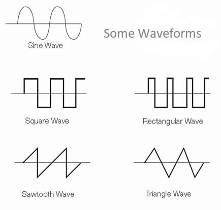
A triangle wave has a symmetrical rise and fall of the waveform, but a sawtooth (also called a ramp oscillator) rises very sharply (ideally instantaneously) and then falls gradually.
Triangle waves contain an infinite number of odd harmonics, which are often used in synthesizing musical sounds. They sound like horns and trombones. They are sometimes used in switch-mode power supplies and motor control circuits. They are often used as time-base or sweep generators and in subtractive audio synthesis as the harmonics are integers and easy to work with digitally.
Sawtooth waves contain an equal amount of even and odd harmonics (unlike square waves which contain only even harmonics that’s why the sound is more musical such as guitar and fuzz box).
One of the easiest ways to generate a triangle wave is from a relaxation oscillator generating a square wave and then integrating it.
Relaxation Oscillators
In the previous article on How to Build a Square Wave Generator, we learned about relaxation oscillators. The sawtooth and triangle wave generators are relaxation oscillators.
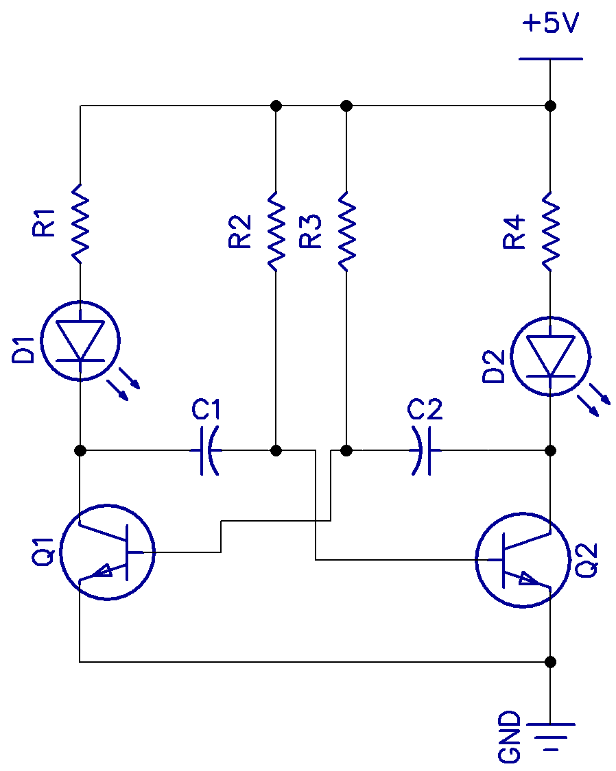
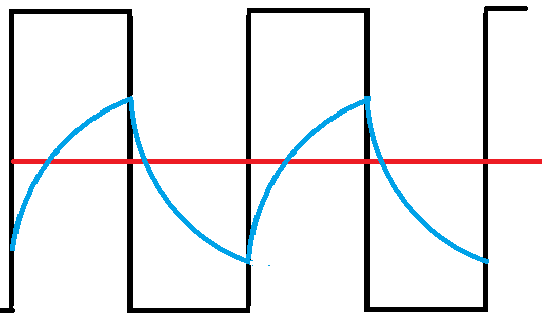
In the waveform above, the blue curve shows the voltage across one of the capacitors. It charges until the trigger point is reached, then discharges again. The black curve is the voltage at the collector, which is the square wave output. In the multivibrator, either collector can be used as the output, although in this circuit, we are just flashing two LEDs alternately.
The waveform across the capacitor looks almost like the triangle wave we are looking for, except that there is a curve to the slope as the capacitor charges and discharges. Adding a constant current source to the charge current could fix this, but there are better ways.
The easiest way to generate a triangle wave is to generate a square wave and then feed it to an integrator.
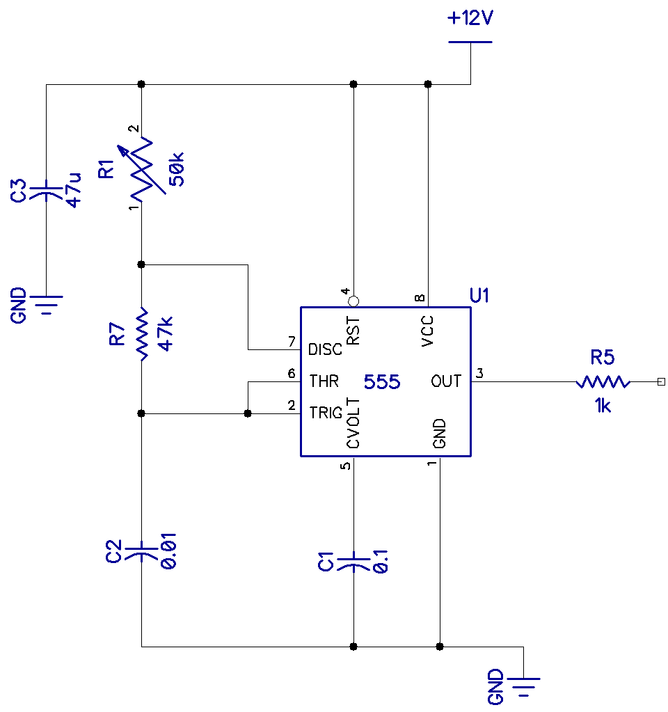
Shown above is a basic square wave oscillator using the famous 555 timer in its astable configuration. This, too, is a relaxation oscillator. R1, R7, and C2 set the frequency, and when R1 and R7 are equal, the mark-space ratio becomes almost equal.
f = 1.44/(R1+2R7)*C = 1000Hz
Below this, on the left side, is a modified circuit to give plenty of variation in the mark-space ratio, which we will use to perfect our triangle wave. R6 sets the mark-space ratio and R2 sets the frequency. By careful adjustment of the mark-space ratio, the time constants on the rising and falling slopes of the triangle waveform of the integrator can be made perfectly symmetrical.
On the right is the integrator. The output of the square wave oscillator is fed into pin 2 of the integrator which converts the square wave into a triangle wave. C3 removes any sharp edge transitions while R3 provides some DC feedback for stability.
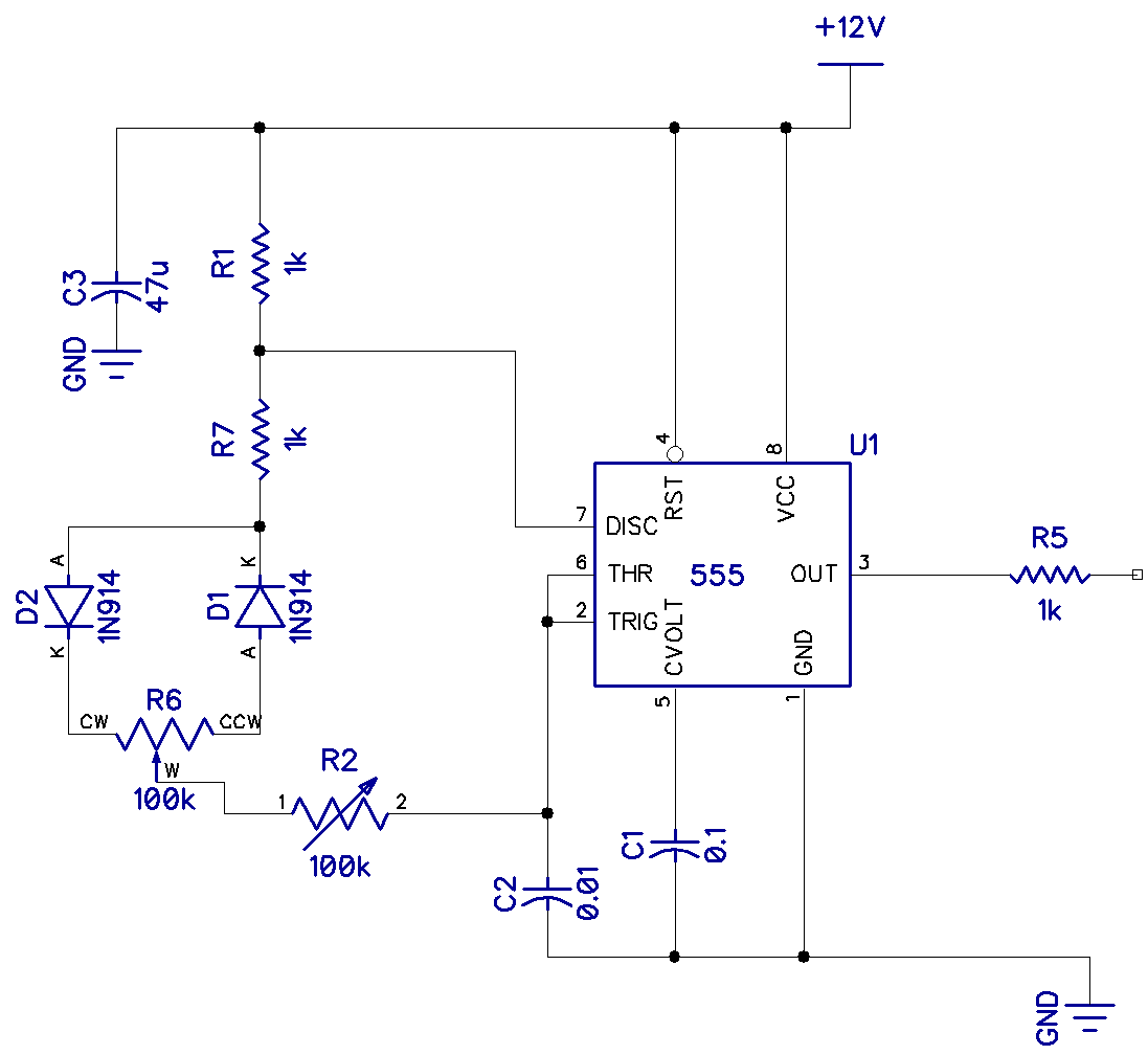 | 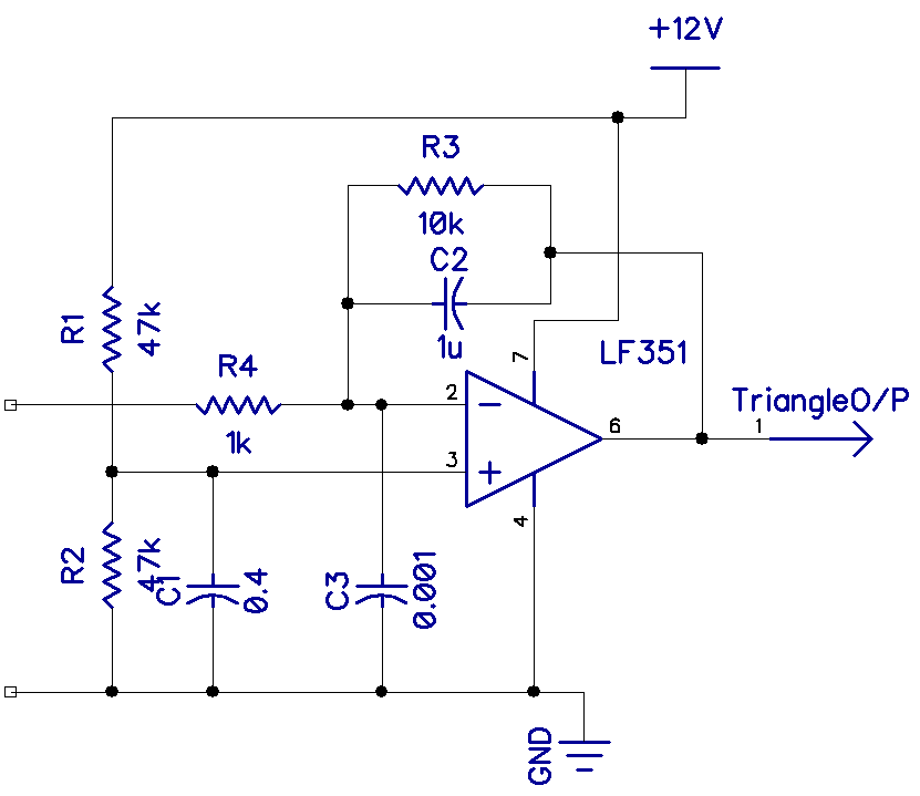 |
| 555 with an adjustable mark-space ratio | Op-amp integrator |
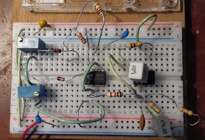 | 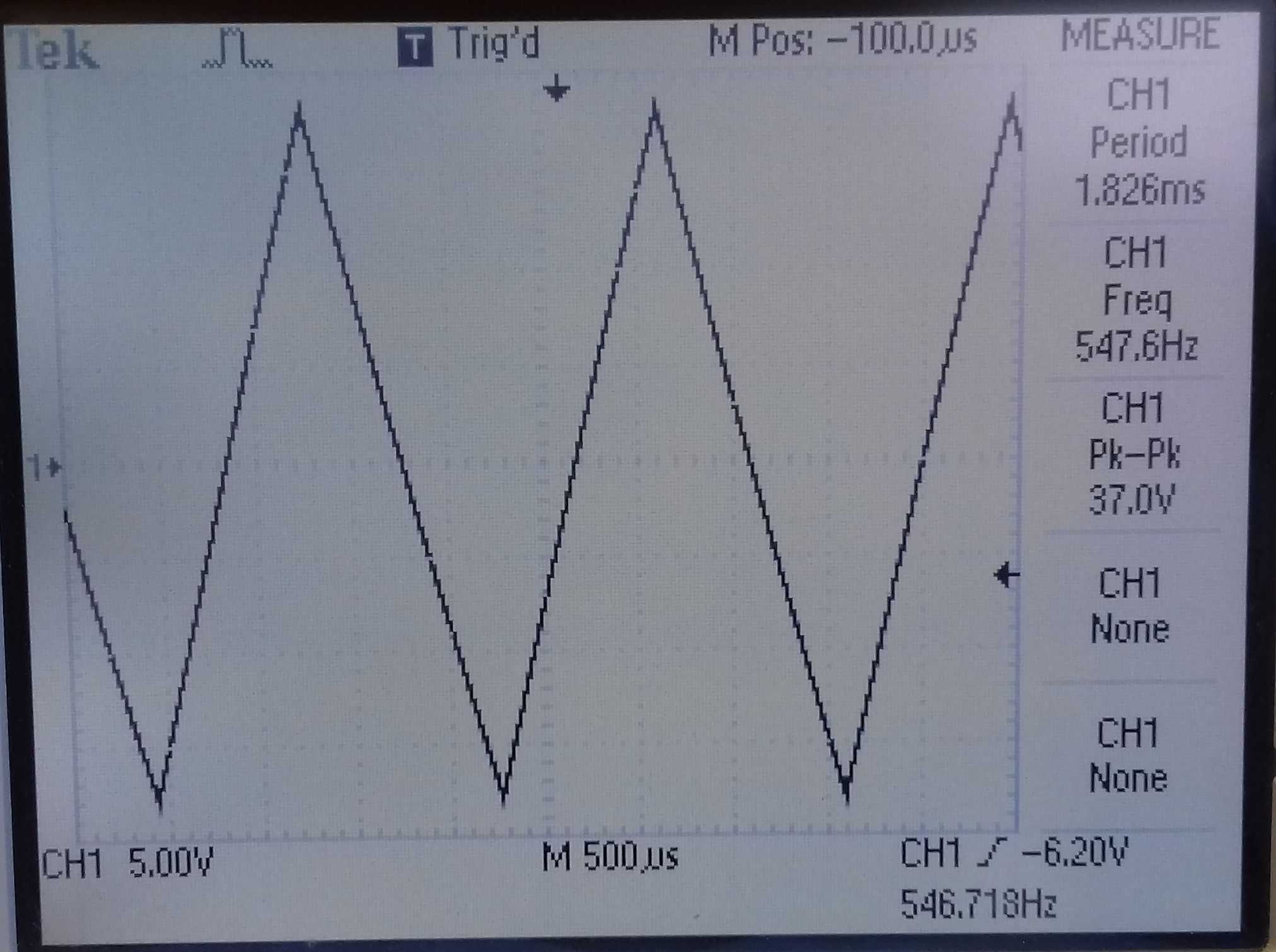 |
| Breadboard of variable mark-space and integrator | Output waveform |
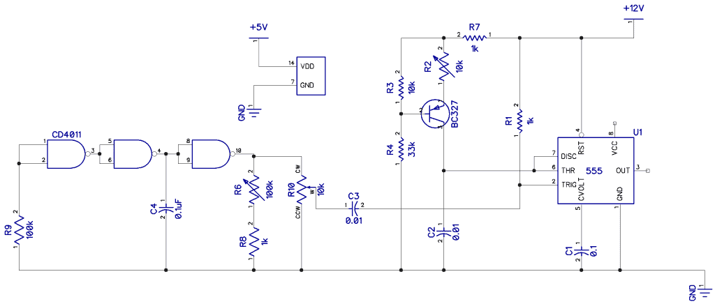
Generating a sawtooth or ramp is a little trickier if you want the rise time to be practically zero and a clean linear slope to the fall. The circuit below features the identical CMOS 4011 square wave oscillator we used in part 1 (square wave oscillators). The square wave output is fed into the trigger input of a 555 configured as a monostable, which fires every time a low going pulse is received at pin 2 (trigger). The charge rate is now controlled by a constant current source (BC327) to linearize the slope of the ramp (we mentioned this earlier).
Shown below is a breadboard of the monostable and the very fine resulting waveform. The frequency is, of course, a function of the square wave generator and is 1/(2.2R6*C4).
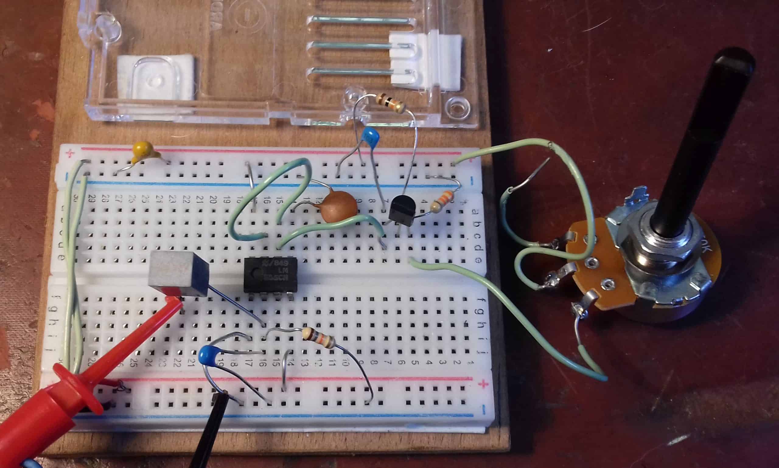 | 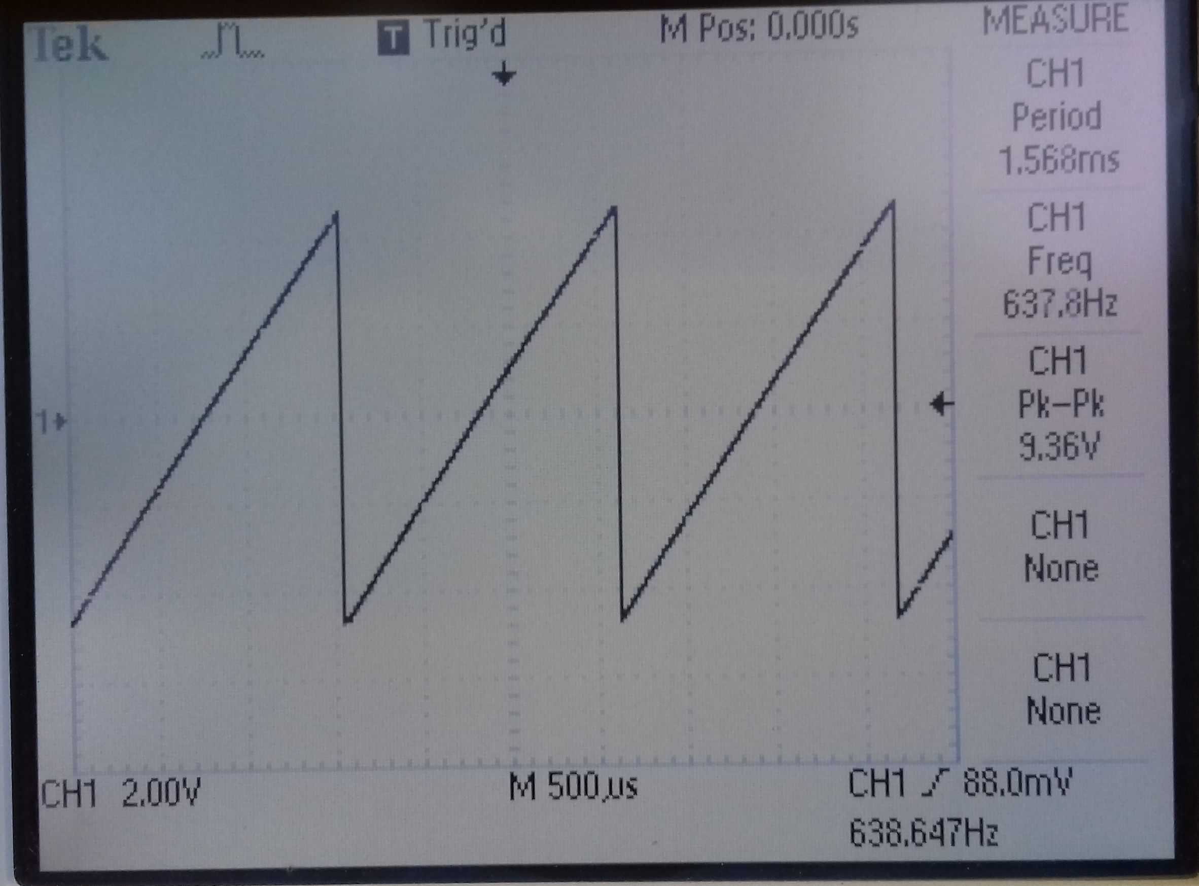 |
| Breadboard of sawtooth oscillator | Output waveform |
Thanks for reading! In part 3, we will look at sine wave oscillators. Be sure to leave a comment below if you have any questions!


Hey Graham ,
the lower part of this page with the 555 as monostable to generate the saw from a trigger is unfortunately very misleading . The transistor is marked as bc327 in the schematic but in the text its a bc237 . the picture you took from the breadboard is showing pin6 of the 555 connected to pin1 on the transistor which would mean its a bc327 if the schematic is conform with the picture you took. the pinout of the transistor in the schematic would be also wrong if its a bc327 as the collector is pin1 . could you please correct text and schematic . or leave a note somewhere.. i have not so much knowledge of electronics but my son was trying to build this and got really frustrated.
Further on the breadboard picture the middle of the pot goes to 12 V ? and the schematic shows no VCC connection to the 555 .