This article is the first in a four-part series on oscillators. We will look at square wave generators in this article, but check out the other articles about sawtooth and triangle wave generators, sine wave generators, and crystal oscillators.
Oscillators
It is an electronic circuit that changes state from positive to negative in a repeating cycle without any stimulus other than DC power. This produces an AC waveform at the output.
Square wave generators
Square wave generators are generally used in electronics and in signal processing. It is just like a Schmitt trigger circuit in which the reference voltage for the comparator depends on the output voltage. It is also said to be an astable multivibrator.
A square-wave generator obviously produces a square wave. However, this may also be adjustable in mark-to-space ratio and is often used for timing, pulsing and clocking circuits. One of the easiest ways to generate a square-wave is by using a relaxation oscillator.
Relaxation oscillators
Relaxation oscillators have two alternating states: a long relaxation period in which the system comes to rest and then a short change-over period in which the stable point flips over to a second stable state for a period then flips back again. The period is set by the time constant which is usually an RC or LC pair.
Some sort of active switching device is needed, such as a transistor pair or a uni-junction transistor or an op-amp comparator, or a custom chip such as a 555 timer. The active device switches between charging and discharging modes, producing a repeating waveform.
For any oscillator to qualify as a relaxation oscillator, it must:
- Produce a non-sinusoidal periodic waveform like triangular, square, or rectangular wave.
- The circuit of a relaxation oscillator must be nonlinear. This means the design of the circuit must use a semiconductor device like a transistor, MOSFET, or op-amp.
- The circuit design must use an energy-storing component like an inductor or capacitor that continuously charges and discharges to produce a cyclic waveform.

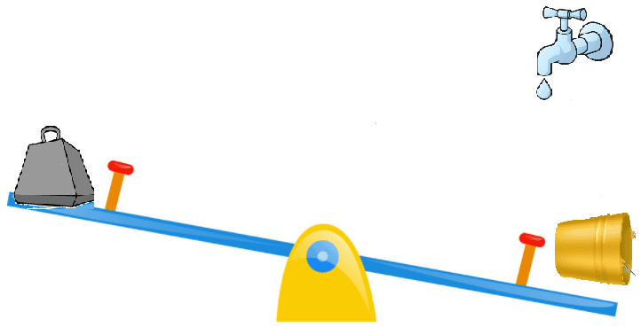
Seesaw A shows the seesaw in a state of equilibrium and at “relaxation,” but as the bucket slowly fills up, a critical tipping point is reached. The state rapidly changes as the bucket end drops and the bucket tips out. As the bucket drains, the left-hand side is now suddenly much heavier and falls to the ground again, and then the bucket lifts and begins to fill again. (Let’s assume it corrects itself again). In an electronic circuit, this is what is happening: a capacitor gets slowly charged through a resistor until a non-linear part of the circuit is reached, causing a sudden discharge, and the cycle begins again.
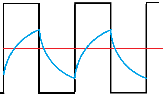
In the waveform above and the multi-vibrator circuit below, the blue curve shows the voltage across one of the capacitors C1. It charges until the bias trigger point is reached, then suddenly turning the other transistor on, then discharges again. The black curve is the voltage at the collector, which is the output. In the multi-vibrator below, either collector can be used as the output. However, in this circuit, we are just flashing two LEDs alternately.
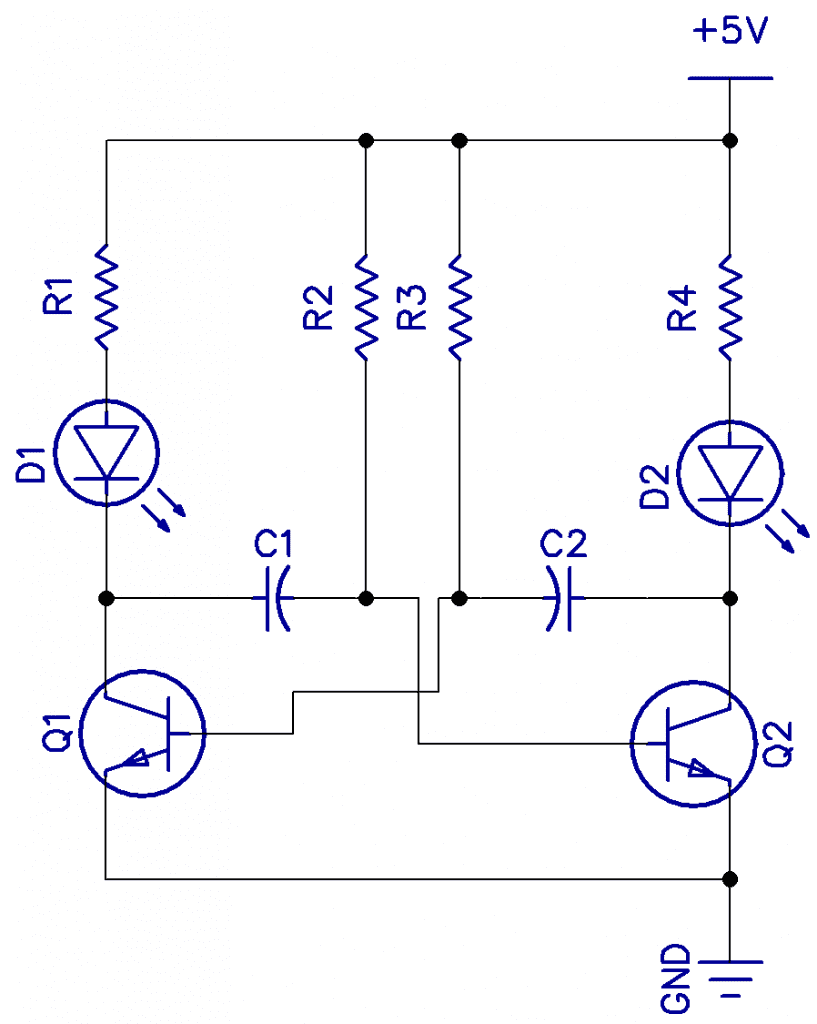
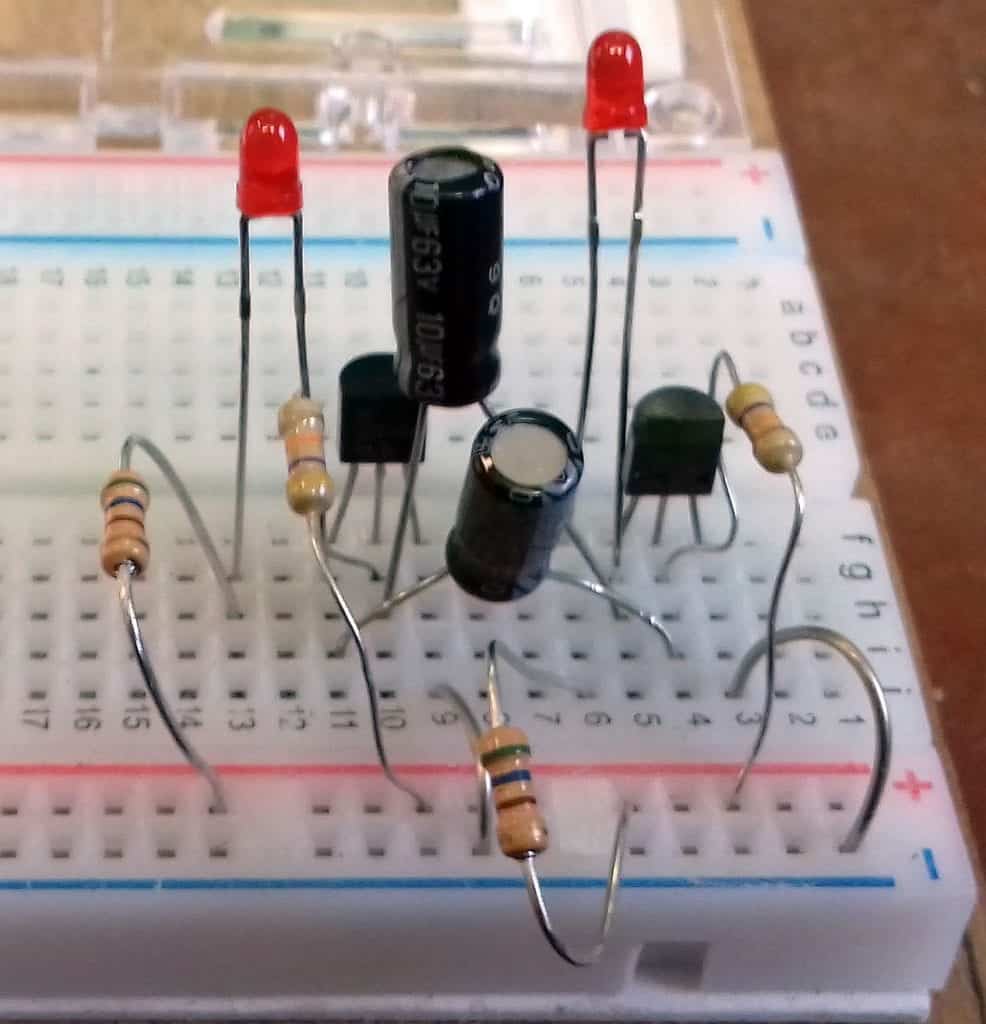
Shown below are the multivibrator circuit and a breadboard lash-up. The two LEDs flash alternately at about 1.5Hz. The transistors are any NPN GP transistors. The mark-space ratio can be varied by changing the C and/or R on one half.
R1 and R4 are 560Ω, R2 and R3 are 47k, and C1 and C2 are 10uF.
Below is the collector voltage waveform.
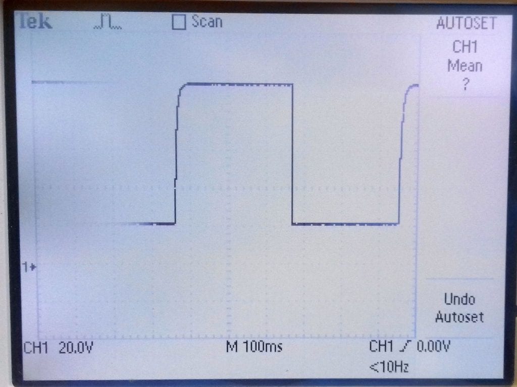
Shown here is the square wave output of the above multivibrator circuit. You can see that the square wave is fairly good, but there is a slight charging delay.
The period of each half is 0.69CR. So if R2 is 47k and C1 is 10uF, that would be 0.32S per half or 0.64 together. Then f = 1/0.64 = 1.5Hz.
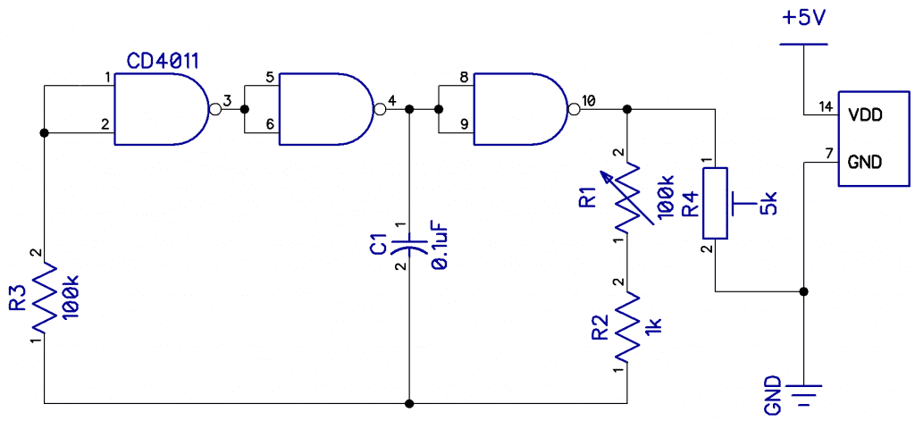
A nice relaxation oscillator can be made from any inverting gates. Although two gates will work (NOR, NAND, OR, Schmitt), three gives a better startup. The frequency is set by R1 and C1:

So, here we have

which gives 45Hz.
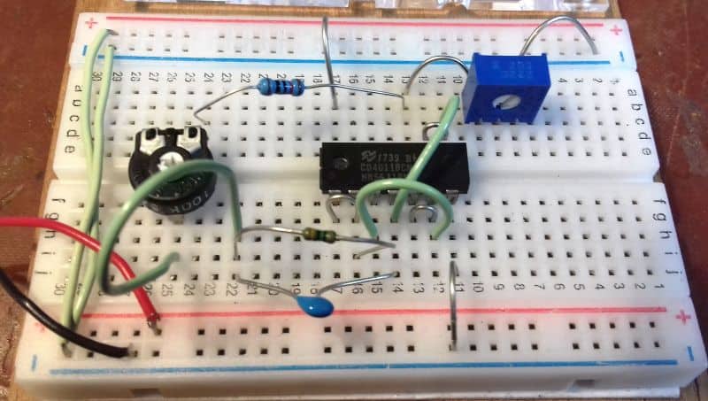
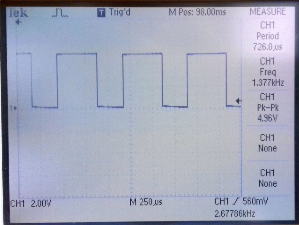
The frequency is adjustable over a 10:1 range and the output is set by R4. R3 is for feedback and is not involved in the timing. The waveform is nice and square.
With R1=100k, C=.004 f=1kHz, C=.04 f=100Hz, C=0.4 f=10Hz.
That’s all for square wave oscillators! A good oscillator can be made from the famous 555 timer and we will look at that in the next article on sawtooth and triangular wave generators. Leave a comment below if you have questions about anything!


Slightly confused. Formulas I have seen and worked with showed TC = RxC. And Frequency = 1 / (2PiRC).
How did f = 1/(2.2RC) come to be?
Barry
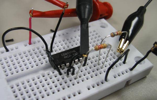
I’m writing regarding the square wave generator shown above using the CD4011.
I did not have a CD4011, so I tried other chips which were quad 2 input NAND gates (74HC00, 74LS00).
I was NOT able to get the circuit to work!!
I used Vcc of 5 Vdc for both the 74 series I tried.
I’m wondering if the CD4000 series are that much different so as to not allow this cicuit to work??
Or, is there some error in the schematic diagram.
I was careful to watch the pinouts that may be different between the chips I tried!
I used all componets shown except, I didn’t have a 0.4 u cap, so I used a 0.47 u cap (electrolytic)
Very useful